Wien Bridge Oscillator
The Wien bridge oscillator is an RC oscillator that uses a Wien bridge circuit as its feedback network.
- The amplifier used in this oscillator is a non-inverting amplifier, which does not introduce any phase shift.
- The feedback network, a Wien bridge circuit, also does not introduce any phase shift.
- Therefore, the phase shift around a loop in a Wien bridge oscillator is .
The figure below shows the basic circuit of the Wien bridge oscillator.
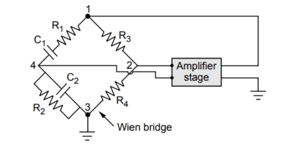
In this setup:
- The output of the amplifier is applied between terminals 1 and 3, while the amplifier is powered from terminals 2 and 4, which is the output of the feedback network.
Derivation of Frequency
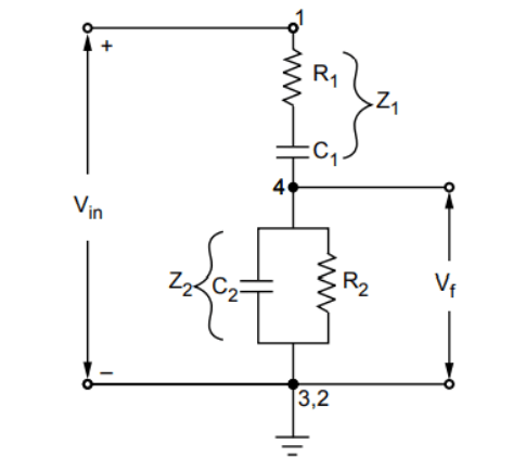
The figure below illustrates the feedback network of the Wien bridge oscillator.
-
The two arms of the feedback network are , (in series) and , (in parallel). These arms are frequency-sensitive and are therefore the focus of this analysis.
-
The input to the feedback network is , applied between terminals 1 and 3, which is the amplifier output.
-
The output of the feedback network is , taken from terminals 2 and 4.
-
This network is also known as a lead-lag network.
-
The voltage across is due to the current .
Using the expressions for and and simplifying:
Rationalizing and simplifying:
-
To achieve zero phase shift, the imaginary part of the above equation must be zero:
but cannot be zero,
-
In practice, if and , then:
Using in equation (i), we get the magnitude of the feedback network as:
-
For sustained oscillations, , hence for the Wien bridge oscillator.
-
Thus, the gain of the amplifier stage must be at least 3 to ensure sustained oscillations.
-
If and , then using in equation (i), we get:
and
Advantages of the Wien Bridge Oscillator
- By mounting the two capacitors on a common shaft and varying their values, the frequency can be adjusted as needed.
- Due to the use of a two-stage amplifier, the gain is high.
- The stability is high.
- It provides stable, low-distortion sinusoidal output.
- The frequency range can be easily selected using decade resistance boxes.
- The circuit is straightforward to design and provides a constant output.
Disadvantages of the Wien Bridge Oscillator
- It cannot generate very high frequencies.
- The circuit requires two transistors and a considerable number of other components.
- The maximum frequency is limited by the amplitude and phase shift characteristics of the amplifiers.
RC Phase Shift Oscillator
RC Phase Shift Oscillator, Analysis of RC Circuit, RC Feedback Network for Phase Shift, Transistorized RC Phase Shift Oscillator, Derivation of Frequency of Oscillations
Operational Amplifiers
Concept of ideal operational amplifiers, ideal operational amplifier parameters, inverting, non-inverting and unity gain amplifiers, adders and subtractor, Differentiator, integrator and Comparator operational amplifiers