Analysis of Magnetic Circuits
Magnetic circuits are similar to normal electrical circuits that have a closed path followed by magnetic lines of force. It is important to know that in a magnetic circuit, the magnetic lines of force originate from a point and end at the same point after completing the full path.
A magnetic circuit consists of magnetic materials which have high permeability, these materials are usually steel or iron. Magnetic circuits also include electric motors, transformers, generators galvanometers, etc.
Ohm's Law For Magnetic Circuits
We have already seen that magnetic circuits are analogous to electric circuits i.e. we can compare magnetic circuits to electric circuits in certain respects. That being said ,we can say that there must be a law analogous to ohm's law for magnetic circuits. This indeed is true that there is a law called Rowland's law which is very similar to ohm's law. The statement of this law is:
Rowland's law states that the number of magnetic lines of force (Φ) is proportional to the magnetomotive force and inversely proportional to the circuit's reluctance .
According to ohm's law,
Here, is the voltage is the current in circuit is circuit resistance. Similarly for magnetic circuits
Here, is the magnetomotive force is the magnetic flux is the reluctance of the material.
The magnetomotive force can be compared to the voltage of the source while the magnetic flux can be compared to the current flow in electric circuit. The magnetic reluctance is synonymous to the resistance in electric circuit. This makes Rowland's law an equivalent version of ohm's law in magnetic circuit.
Properties of Magnetic Circuits
There are two major properties of magnetic circuits namely magnetic flux and magnetomotive force .
-
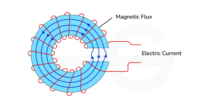
Magnetic Flux: Magnetic Flux is the term used for defining magnetic induction in magnetic circuits. It is often referred to when discussion is about strength of magnetic field in a particular region. Formally magnetic flux can be defined as a quantitative measure of magnetic field lines passing through a given region. It is generally represented by symbol Φ and can be written as
Where,
- Φ is the magnetic flux measured in Weber (Wb), B is the magnetic field strength measured in Tesla (T),
- A is the area of magnetic field lines measured in square meters (m²),
- θ is the angle between the magnetic field lines and the normal to the surface.
-
Magnetomotive Force (MMF): This concept comes into picture when we talk about maintaining magnetic flux in a magnetic circuit. Similar to electromotive force in electrical circuits we talk about MMF as an analogous force. This is an important force that helps in sustaining the magnetic circuit. Formally, It is the total magnetic potential difference in a magnetic circuit and which performs the task of maintaining magnetic flux in a magnetic circuit. It can be written as
F is the magnetomotive force in ampere-turns, N is the number of turns of the coil or winding, I is the current flowing through the coil in amperes.
Difference Between Electric Circuit and Magnetic Circuit
| Electric Circuits | Magnetic Circuits |
|---|---|
| It is the path for electric current to flow. | It is the path traced by magnetic flux. |
| It follows Ohm's law . | It follows a law analogous to Ohm's law . |
| The force involved in maintaining circuits is electromotive force. | The force involved in maintaining circuits is magnetomotive force. |
| Resistance opposes the flow of current. | Reluctance is opposed by the magnetic path to flux. |
| The flow of electrons decides current in the conductor. | The magnetic lines of force decide the flux in the core. |
Advantages of Magnetic Circuits
- Magnetic circuits are efficient in terms of energy transfer between components of the circuit. Transformers are some devices which use magnetic circuits for transfer of electrical energy between coils. They help to increase efficiency by using magnetic cores with high permeability.
- Designing of magnetic circuits can be versatile depending on our needs. Based on the requirements of certain devices we can select different core materials, wire thickness, shapes, and sizes. This makes magnetic circuits a common choice of use.
- Magnetic circuits provide a way to perform electrical isolation and voltage management in electrical devices like transformers.
- Although magnetic circuits don't completely remove eddy currents but they can be reduced by magnetic circuits. The presence of laminated cores in magnetic circuits improves the overall efficiency of circuit by reducing eddy currents.
- Magnetic circuit helps regulating the performance of circuit by giving direct access to the magnetic properties of system like magnetic flux.
Disadvantages of Magnetic Circuits
- The major disadvantage associated with magnetic circuits is the hysteresis loss associated with losses due to the magnetic core in the circuit. This loss occurs due to the energy which is used to magnetize and demagnetize the core material.
- Another loss associated with magnetic circuits is Eddy Current Loss. In appliances that work with high-frequency, eddy current losses can still be a significant factor leading to additional problems like power loss, unnecessary heating.
- The cost of manufacturing these circuits can be high due to various components involved like magnetic core, wiring and other components which are expensive.
- The properties of magnetic circuit depends largely on factors like temperature . This is because the core inside circuit is made up of permeable material whose magnetic properties are temperature dependent. Thereby affecting performance and efficiency of magnetic circuits.
AC excitation of Magnetic Circuits
Magnetic circuits are similar to electric circuits but instead of electrical currents, they involve magnetic flux. AC excitation in magnetic circuits means applying an alternating current (AC) to create a time-varying magnetic field within the magnetic material. This is a fundamental concept in transformers, inductors, and various electromagnetic devices.
Key Concepts
-
Magnetic Flux (Φ):
- The magnetic flux is the total magnetic field (B) passing through a given area (A).
-
Magnetic Field Intensity (H):
- The magnetomotive force (MMF) per unit length of the magnetic path.
- where N is the number of turns, I is the current, and is the length of the magnetic path.
-
Magnetic Permeability (μ):
- A measure of how easily a material can support the formation of a magnetic field within itself.
- where B is the magnetic flux density and H is the magnetic field intensity.
-
Reluctance (R):
- The opposition to the creation of magnetic flux in a magnetic circuit.
- where l is the length of the magnetic path, μ is the permeability, and A is the cross-sectional area.
Magnetic Circuit Analysis with AC Excitation
To analyze a magnetic circuit with AC excitation, consider the following steps:
- Determine the MMF: Calculate the magnetomotive force using the AC current and the number of turns.
- Calculate Magnetic Flux: Use the magnetic circuit's reluctance to determine the magnetic flux.
- Induced EMF: Calculate the induced EMF in the coil.
- Core Losses: Calculate the hysteresis and eddy current losses based on the material properties and the frequency of the AC excitation.
Iron Losses
Iron losses, also known as core losses, occur in the magnetic material of transformers, inductors, and other electromagnetic devices. These losses arise from the alternating magnetic field applied to the core and consist primarily of two components: hysteresis losses and eddy current losses.
Components of Iron Losses
-
Hysteresis Losses:
- Hysteresis losses are caused by the lagging behavior of the magnetic flux density (B) behind the magnetic field intensity (H) as the magnetic material undergoes cyclic magnetization.
- Each time the magnetic field reverses direction, energy is lost due to the internal friction of the magnetic domains realigning. where, η is the Steinmetz coefficient, is the maximum flux density, f is the frequency, n is the Steinmetz exponent (typically between 1.5 and 2.5), and V is the volume of the core material.
-
Eddy Current Losses:
- Eddy current losses are caused by circulating currents induced within the conductive core material due to the changing magnetic field.
- These currents create their own magnetic fields, which oppose the original magnetic field and result in resistive heating within the core. where is the maximum flux density, t is the thickness of the core laminations, f is the frequency, V is the volume of the core material, and ρ is the electrical resistivity of the core material.
-
Total Iron Losses: The total iron losses are the sum of the hysteresis losses and eddy current losses
Minimizing Iron Losses
To reduce iron losses in magnetic circuits, consider the following strategies:
-
Material Selection:
- Use materials with high magnetic permeability and low hysteresis loss, such as silicon steel or ferrites.
- These materials have narrower hysteresis loops, which reduce hysteresis losses.
-
Lamination:
- Laminating the core reduces eddy current losses by increasing the electrical resistance of the core.
- Thin laminations separated by insulating layers prevent large eddy currents from forming.
-
Core Design:
- Optimize the core shape and size to minimize the path length of the magnetic flux and reduce the volume of the core material.
- Use distributed air gaps to control the flux distribution and minimize localized losses.
-
Frequency Management:
- Operating at lower frequencies reduces both hysteresis and eddy current losses.
- In high-frequency applications, use materials specifically designed for low-loss performance at those frequencies.
Fringning and Stacking
Fringing and stacking are important concepts related to the design and performance of magnetic circuits, particularly in transformers and inductors. Understanding these phenomena helps in optimizing the efficiency and effectiveness of these devices.
Fringing
Fringing occurs when the magnetic flux lines spread out as they pass through the air gaps in a magnetic circuit. This effect can impact the magnetic circuit's performance, especially in devices like transformers and inductors with gapped cores.
Effects of Fringing
-
Increased Effective Area:
- The effective cross-sectional area of the magnetic path increases due to the spreading of flux lines.
- This can lead to a decrease in the reluctance of the magnetic path in the vicinity of the air gap.
-
Flux Leakage:
- Some of the magnetic flux may leak out of the intended path, which can reduce the efficiency of the magnetic circuit.
-
Non-uniform Flux Density:
- The flux density becomes non-uniform near the air gap, which can affect the performance of the device.
Stacking
Stacking refers to the assembly of thin laminated sheets of magnetic material to form the core of transformers, inductors, and other electromagnetic devices. This method is used to reduce eddy current losses and improve the magnetic properties of the core.
Effects of Stacking
-
Reduced Eddy Current Losses:
- Laminations increase the electrical resistance of the core, which reduces the magnitude of eddy currents and thereby minimizes eddy current losses.
-
Improved Magnetic Properties:
- Laminations made from high-quality magnetic materials, such as silicon steel, enhance the magnetic properties of the core, leading to better performance.
-
Structural Integrity:
- Stacking provides structural stability to the core, making it more robust and durable.
Applications: Solenoids And Relays
Solenoids
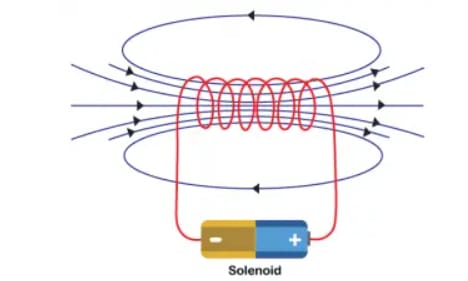
A solenoid is an electromechanical device consisting of a coil of wire that generates a magnetic field when an electric current passes through it. This magnetic field can be used to create linear motion or actuation. Solenoids are fundamental components in various applications requiring controlled movement or switching.
Structure and Operation
- Coil: The solenoid consists of a helical coil of wire, usually made of copper, which acts as an electromagnet when an electric current flows through it.
- Core (Plunger): A movable ferromagnetic core or plunger is placed inside the coil. When the coil is energized, the magnetic field pulls the core into the coil.
- Spring: Often, a spring is used to return the core to its original position when the current is turned off.
Basic Principle
- When an electric current flows through the coil, it creates a magnetic field.
- The magnetic field exerts a force on the ferromagnetic core, causing it to move.
- This movement can be used to perform mechanical tasks, such as opening a valve or actuating a switch.
Types of Solenoids
-
Linear Solenoids:
- These solenoids produce linear motion. The core or plunger moves in a straight line.
- Applications include door locks, actuators, and valve controls.
-
Rotary Solenoids:
- These solenoids produce rotational motion instead of linear motion.
- Applications include various switchgear and control mechanisms.
-
Push and Pull Solenoids:
- Push Solenoids: The core is pushed out when the solenoid is energized.
- Pull Solenoids: The core is pulled in when the solenoid is energized.
Solenoids are versatile and widely used electromechanical devices that convert electrical energy into mechanical motion. Their ability to create controlled linear or rotary motion makes them essential components in automotive systems, industrial automation, home appliances, medical devices, consumer electronics, and security systems. Proper selection and design of solenoids based on electrical, mechanical, and environmental requirements ensure optimal performance and longevity in their intended applications.
Relays
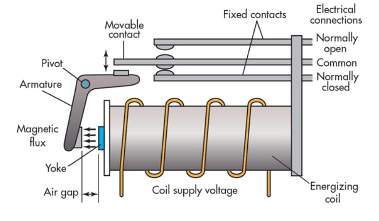
A relay is an electromechanical switch that uses an electromagnetic coil to open or close one or more sets of contacts. This allows a low-power signal to control a high-power circuit, enabling a wide range of applications in various electrical and electronic systems.
Structure and Operation
- Electromagnetic Coil: When energized by an electric current, the coil generates a magnetic field.
- Armature: A movable metal piece that is attracted by the magnetic field generated by the coil.
- Spring: Returns the armature to its original position when the coil is de-energized.
- Contacts: Conductive pieces that open or close the electrical circuit. Relays can have multiple sets of contacts, such as normally open (NO) and normally closed (NC).
Basic Principle
- When current flows through the coil, it creates a magnetic field.
- The magnetic field attracts the armature, causing it to move and change the state of the contacts.
- This movement opens or closes the circuit, allowing or stopping the flow of current through the load.
Types of Relays
-
Electromechanical Relays:
- Operate using a physical moving armature and contacts.
- Suitable for high current and high voltage applications.
-
Solid State Relays (SSRs):
- Use semiconductor devices instead of moving parts.
- Faster switching, longer lifespan, and less noise but typically handle lower currents compared to electromechanical relays.
-
Reed Relays:
- Use a small, magnetically actuated reed switch enclosed in a glass capsule.
- Suitable for switching low current signals and used in telecommunications and instrumentation.
-
Time-Delay Relays:
- Incorporate a timing mechanism that delays the opening or closing of contacts.
- Used in applications requiring precise timing control, such as in industrial automation and lighting systems.
Relays are versatile and essential components in a wide range of applications, from automotive systems and home appliances to industrial control systems and telecommunications. They enable the control of high-power circuits with low-power signals, providing isolation and protection for both control and output circuits.
Electromagnetic Induction
Electromagnetic induction, Faraday law of Electromagnetic Induction, Applications of Electromagnetic Induction , Dot convention, Equivalent inductance
Single Phase Transformers
Constructional features of transformer, operating principle and applications, equivalent circuit, phasor analysis and calculation of performance indices.