AC Circuit
AC circuits are electrical circuits powered by alternating current, where the voltage and current periodically change direction and magnitude. Unlike direct current (DC) circuits, where current flows in one direction, AC circuits have a sinusoidal waveform where the voltage and current oscillate back and forth.
Key Characteristics of AC Circuits:
- Frequency (f): The number of cycles the voltage or current completes in one second, measured in Hertz (Hz).
- Period (T): The time taken for one complete cycle of the AC waveform, measured in seconds.
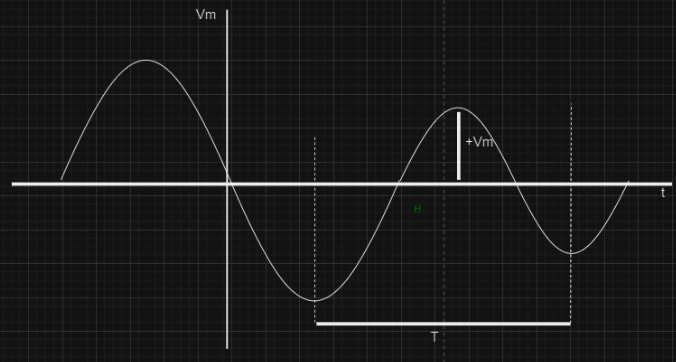
- Amplitude (A): The maximum value of the voltage or current in the AC waveform.
- Phase (φ): The angular difference between the voltage and current waveforms, representing how they are aligned in time.
Components of AC Circuits:
The primary components found in AC circuits include:
- Resistors (R): Provide opposition to the flow of current and dissipate electrical energy as heat.
- Capacitors (C): Store electrical energy in an electric field and oppose changes in voltage.
- Inductors (L): Store electrical energy in a magnetic field and oppose changes in current.
Sinusoidal Sources
Sinusoidal sources are essential in analyzing AC (alternating current) circuits and signal processing.
Characterstics:
- Waveform: A sinusoidal source produces a waveform that can be described mathematically by a sine or cosine function.
- Frequency: The frequency (f) of the sinusoidal wave is the number of cycles it completes per second, measured in Hertz (Hz).
- Amplitude: The amplitude (A) is the peak value of the waveform.
- Phase: The phase (ϕ) indicates the horizontal shift of the waveform from a reference point.
Mathematical Representation: A sinusoidal source can be represented as:
or
where:
- v(t) is the voltage or current as a function of time (t),
- A is the amplitude,
- f is the frequency,
- ϕ is the phase angle.
RC, RL and RLC Circuits
RC Circuits
An RC circuit is a unique sort of circuit that includes a resistor and a capacitor. This sort of circuit consists of two major components that can be linked in either series or parallel. This circuit will consume energy due to the presence of a resistor. The circuit can be powered by either a voltage or current source. The capacitor in the circuit stores energy through charging and discharging, resulting in a change in the circuit's temporal behavior.
Resistor: A resistor is a passive electrical component that provides resistance to the flow of electric current. It is one of the fundamental components in electronic circuits, used to control the current and voltage levels, divide voltages, and dissipate power. Resistance is the fundamental property of which opposes the flow of current.
There are many factors that affects the resistance like :
- Different Materials have different resistivity.
- The length of the conductor also affect resistance.
- The cross sectional area of a conductor Where, is a constant called resistivity.
Capacitor: A capacitor is a passive electronic component that stores energy in an electric field. It consists of two conductive plates separated by an insulating material called the dielectric. Capacitors are widely used in electronic circuits for various functions including filtering, coupling, decoupling, and energy storage.
Capacitance is the property of capacitor which is measured in farads(F). It stores the energy in electric field. The value of capacitance is dependent on the dielectric material present between the plates.
Where, ε is the permittivity of the material that is present between the plates.
Types of RC Circuits
Depending on the arrangement of Resistor and Capacitor the circuits can be of two types:
- Series RC Circuits
- Parallel RC Circuits
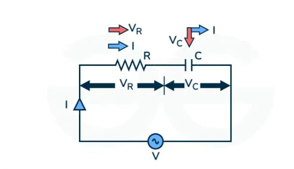
Series RC Circuits
In this type of circuit, a resistor and capacitor are connected in series.
Where,
- I is the RMS value of the current in the circuit.
- is the voltage across the resistor R.
- is the voltage across the capacitor.
- is the RMS value of the supply voltage.
Applying KVL in clockwise direction,
We know, and
Applying KVL,
Since Current is same throughout the circuit in series connection we can current as the rate of change of charge with respect to time,
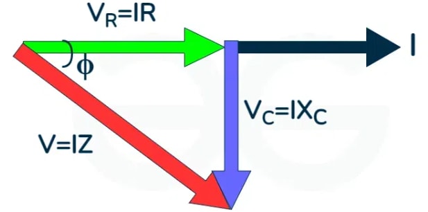
Steps to draw phasor diagram:
-
We determine the vector components in the circuit.
-
Then we take reference. As the circuit is in series and by the property of series the current is same throughout so it is taken as reference.
-
We have as the and are in phase with each other. But will have lesser magnitude.
-
is drawn perpendicular to I as the capacitor is 900 out of phase of each other and is lagging behind.
-
The vector sum of the and , is given by and it has an angle of which is the power factor angle.
When we take the vector sum we get the following,
is the impedance of the RC series Circuit,
where,
The above figures are the voltage and impedance triangle. From these figures we can see that lags by an Angle . So we can write,
So we can say that in a RC series circuit current leads the voltage by angle.
Power
where, is the constant part and is the variable component.
The average power consumed by the circuit is
The power factor is
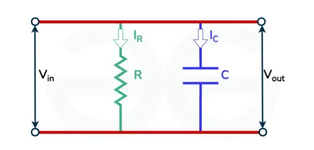
Parallel RC Circuits
In this type of circuit, a resistor and capacitor are connected in parallel combination.
where,
- is the input voltage.
- is the output voltage.
- is the current across the resistor.
- is the current across the capacitor.
In parallel combination the voltage drop across both the elements remains same and using KCL we can say that . Also, .
Using the ohm’s law,
and, .
therefore,
Impedance of the RC parallel circuit is
The transfer function of the parallel RC circuit is,
RC Circuit Current
RC Circuit Voltage
Across Capacitor,
Across Resistor,
Advantages of RC Circuits:
- RC circuits are relatively easy to design and construct.
- The components used in RC circuits (resistors and capacitors) are generally low-cost, making these circuits economical to implement.
- Capacitors in RC circuits can store and release energy, which can be useful in power supply smoothing and energy storage applications.
- RC circuits can be used to create frequency-selective networks, which are crucial in applications like audio equalizers and radio receivers.
- The behavior of RC circuits is well understood and can be easily predicted using standard circuit analysis techniques, which makes them reliable for many applications.
Disadvantages of RC Circuits:
- RC circuits are not suitable for high-power applications. The power dissipation in resistors can lead to significant energy losses, especially at higher currents.
- RC circuits are not effective at very high frequencies. The reactance of capacitors decreases with increasing frequency, which can limit the circuit's effectiveness.
- The performance of RC circuits can be affected by temperature variations.
Numericals
RL Circuits
Resistor-Inductor (RL) circuits are fundamental electrical circuits consisting of resistors (R) and inductors (L) connected in series or parallel. These circuits are crucial in understanding the behavior of inductive components in AC and DC circuits.
Resistor: A resistor is a passive electrical component that provides resistance to the flow of electric current. It is one of the fundamental components in electronic circuits, used to control the current and voltage levels, divide voltages, and dissipate power. Resistance is the fundamental property of which opposes the flow of current.
There are many factors that affects the resistance like :
- Different Materials have different resistivity.
- The length of the conductor also affect resistance.
- The cross sectional area of a conductor Where, is a costant called resistivity.
Inductor: An inductor is a passive electrical component that stores energy in its magnetic field when electric current flows through it. The inductance L is measured in henrys (H). In an RL circuit, the inductor opposes changes in current flow, creating a voltage drop that is proportional to the rate of change of the current through it
Types of RL Circuits
Depending on the arrangement of Resistor and Iductor the circuits can be of two types:
- Series RL Circuits
- Parallel RL Circuits
Series RL Circuits
A circuit that contains a resistance R connected in series with the coil having an inductance L is known as an RL Series Circuit. When a supply voltage (V) is applied across the current element I flowing in the circuit. and are the currents flowing in the inductor and resistor, but the current flowing across both the elements are the same as they are said to be connected in the series connection with each other.
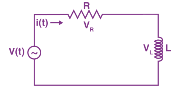
Where, is voltage across resistor R. is voltage across inductor L. V(t) is the total voltage across the circuit.
In series RL circuit, the values of frequency , voltage , resistance and inductance are known and there is no instrument for directly measuring the value of inductive reactance and impedance; so, for complete analysis of series RL circuit, follow these simple steps:
Step 1. Since the value of frequency and inductor are known, so firstly calculate the value of inductive reactance ohms.
Step 2. From the value of and , calculate the total impedance of the circuit which is given by,
Step 3. Calculate the total phase angle for the circuit .
Step 4. Use Ohm’s Law and find the value of the total current: amp.
Step 5. Calculate the voltages across resistor and inductor by using Ohm’s Law. Since the resistor and the inductor are connected in series, so current in them remains the same.
and,
Power in RL Series Circuit
Alternating Voltage across the circuit is given as,
Current can be given as,
So, the instantaneous power is given by the Equation,
Now substituting the value of and from the above equation,
So, the average power consumed in one cycle in the circuit can be given by,
So, can be calculated as,
Where is the power factor
can be calculated as,
Now substituting this value we will get,
Power consumed in the circuit is .
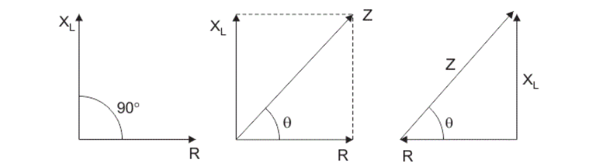
Impedance (Z)
The total impedance in a series RL circuit is given by:
where is the inductive reactance and is the angular frequency , with (f) being the frequency of the AC source.
Voltage and Current Relationship
- The voltage across the resistor is in phase with the current.
- The voltage across the inductor leads the current by 90 degrees.
- The total voltage is the phasor sum of and .
Parallel RL Circuits
An RL parallel circuit is formed when a resistor and an inductor are connected in parallel and driven by the same voltage source. Unless it is powered by a current source, the parallel RL circuit is generally less interesting than the series circuit. This is mostly because this circuit does not act as a voltage input filter. After all, the output voltage (Vout) and input voltage (Vin) are equal.
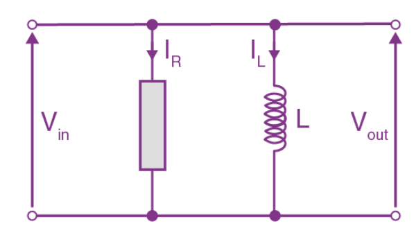
where,
- is the input voltage.
- is the output voltage.
- is the current across the resistor.
- is the current across the inductor.
Impedance (Z)
The total impedance in a parallel RL circuit is given by:
where is the inductive reactance.
Voltage and Current Relationship:
- The voltage across both the resistor and the inductor is the same.
- The current through the resistor (I_R) is in phase with the voltage.
- The current through the inductor (I_L) lags the voltage by 90 degrees.
Currents in the Circuit
The total current (I) is the phasor sum of the currents through the resistor and the inductor
where and
Power
The real power (P) consumed in the circuit is due to the resistor and is given by:
Advantages of RL Circuits:
- RL circuits provide inductive reactance, which is useful in various applications such as tuning and impedance matching in RF (radio frequency) and communication systems.
- Inductors store energy in their magnetic field, which can be advantageous in applications requiring energy storage and release, such as in power supplies and energy management systems.
- RL circuits can be used to regulate current. Inductors oppose changes in current, which can help in maintaining a steady current flow in power supply applications.
- RL circuits can introduce a phase shift between voltage and current, which is useful in AC analysis, power factor correction, and in designing phase shift networks and oscillators.
- nductors perform well at high frequencies, making RL circuits suitable for high-frequency applications like RF circuits, filters, and communication systems.
Disadvantages of RL Circuits:
- Inductors can be large and heavy, especially those designed to handle high currents or store significant amounts of energy.
- Inductors can be more expensive than resistors and capacitors, particularly those with high inductance values or those designed to handle high currents.
- The inductance of an inductor can change with temperature, which can affect the performance and stability of the circuit.
Numericals
RLC Circuits
An RLC circuit is an electrical circuit consisting of resistors (R), inductors (L), and capacitors (C) connected in series or parallel. These circuits are fundamental in the analysis of AC (alternating current) circuits, resonance phenomena, and transient responses.
Components of RLC Circuits:
- Resistor(R): Opposes the flow of electric current, causing a voltage drop proportional to the current.Resistance R is measured in ohms (Ω).
- Inductor(L): Stores energy in a magnetic field when current flows through it and opposes changes in current.Inductance L is measured in henrys (H).
- Capacitor(C): Stores energy in an electric field when a voltage is applied across its terminals and opposes changes in voltage.Capacitance C is measured in farads (F).
Resistor (R), Inductor (L), and Capacitor (C) are the passive elements.If an AC source is present in any electrical network/circuit, it is known as an AC network/circuit. Since we have two basic connections, we will have two types of RLC circuits.
- Series RLC Circuit
- Parallel RLC Circuit
Series RLC Circuit
In the series RLC circuit,Resistor (R), Inductor (L), and Capacitor (C) all in series. It is also called the RLC circuit in series. We know that the current is the same in series whereas the supply voltage (AC) gets divided among the passive elements.
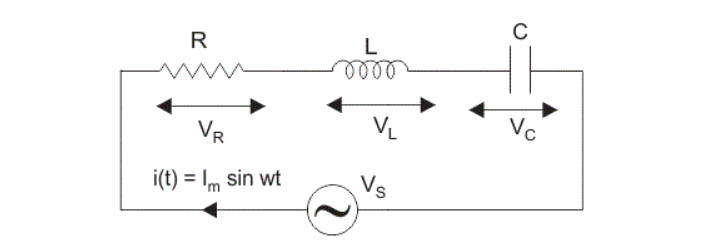
Where,
- be the voltage across resistor, R.
- be the voltage across inductor, L.
- be the voltage across capacitor, C.
- be the inductive reactance.
- be the capacitive reactance.
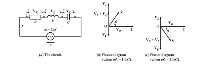
Writing KVL equation, we get applied voltage as,
where, Z is the complex impedance of the given circuit. We can write,
or
or
Usually, we take the applied voltage as the reference phasor, i.e., . In such case the resulting current I is given as
In a series RLC circuit, one cannot definitely say whether the current lags or leads the applied voltage. It depends upon the relative values of the terms and . There can be following three possibilities:
-
When : The phase angle of the current phasor is negative (see Eq.(iv)). The current lags the voltage. The circuit behaves as an inductive circuit.
-
When : The phase angle of the current phasor is positive (see Eq.(iv)). The current leads the voltage. The circuit behaves as a capacitive circuit.
-
When : The phase angle . The current is in phase with voltage. The circuit behaves as a purely resistive circuit. This is a special case, and is called resonance. We shall talk about this phenomenon a little later.
Parallel RLC Circuit
In a parallel RLC Circuit, the resistor, inductor, and capacitor are all connected across the same voltage supply but operate independently, with the voltage constant across each and the total current split among them.
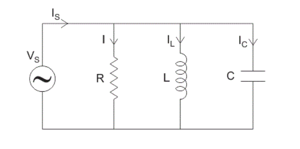
Where,
- is the supply current in amps.
- is the current flowing in the inductor, L in amps.
- is the current flowing in the capacitor, C in amps.
- is the current flowing in the resistor, R in amps.
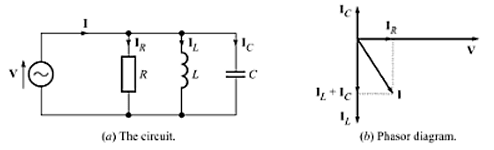
Figure. shows a parallel RLC circuit. Writing KCL equation, we get total current supplied by the applied voltage as
or
where, is the complex admittance of the given circuit. Obviously,
Note that (+j) is associated with and not with and with . The complex admittance of the circuit can be written as,
Take the applied voltage as the reference phasor, i.e., , the resulting current can be written as,
Advantages of RLC Circuits:
- Ability to resonate at a specific frequency, useful in many electronic applications.
- Can be used to create various filter types and oscillators.
- Useful in achieving impedance matching in communication systems for efficient power transfer.
- Both inductors and capacitors store energy, providing functionality in power management and signal processing.
Disadvantages of RLC Circuits:
- More complex to analyze and design compared to simpler RC or RL circuits due to the interaction of resistive, inductive, and capacitive components.
- Inductors, in particular, can be large and heavy, especially for low-frequency applications.
- Power dissipation in the resistor can be significant, especially at high currents or voltages.
Numericals
Question A choke coil is connected to a 240-V ac supply. When the frequency of the supply is 50 Hz, an ammeter connected in series with the choke reads 60 A. On increasing the frequency of the ac supply to 100 Hz, the same ammeter reads 40 A. Calculate the resistance and inductance of the coil.
Solution: On changing the frequency of the ac supply, only the reactance part of the choke changes. Thus,
Subtracting Eq. (i) from Eq. (ii), we get
Question: For the circuit shown in Fig.(a), calculate (a) the impedance, (b) the current, (c) the phase angle, (d) the voltage across each element, (e) the power factor, (f) the apparent power, and (g) the average power. Also, draw the phasor diagram for the circuit.
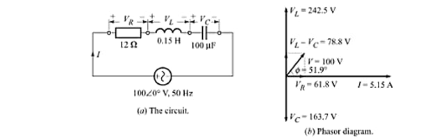
Solution:
(a) The impedance,
(b) The current,
(c) The phase angle,
(d) The voltage,
(e) The power factor, lagging
(f) The apparent power
(g) The average power
The phasor diagram is given in Fig.(b).
Inductor in DC Circuit
Inductor energization and de-energization, inductance current-voltage relationship, time-constant; Transient responseof RL, RC and RLC Circuits
Phasors
Concept of Phasors, Phasor representation of circuit elements, Complex notation representation, Single phase AC Series and parallel circuits, power dissipation in AC circuits, power factor correction, Resonance in series and parallel circuits