Concept of Phasors
Phasors are a mathematical representation used to simplify the analysis of sinusoidal signals,They are especially useful in analyzing AC circuits. A phasor converts a sinusoidal function, which varies with time, into a complex number that represents its magnitude and phase.
Properties of Phasors:
- The length of a phasor is proportional to the maximum value of the alternating quantity involved.
- The projection of a phasor on the vertical axis gives the instantaneous value of the alternating quantity involved.
Phasor Diagram:
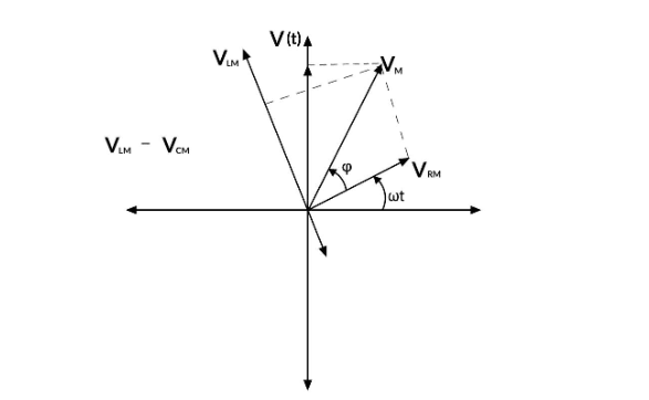
Phasor Diagrams are a graphical way of representing the magnitude and directional relationship between two or more alternating quantities.
A phasor can be a scaled line whose length specifies an AC quantity with magnitude (peak amplitude) and direction (phase) that is frozen at a specific instant in time. A phasor diagram represents the phase connection between two or more sine waves with the same frequency. In a phasor diagram, phasors are represented by open arrows that rotate counterclockwise at an angular frequency of ω around the origin.
Phasor Representaion Of Circuit Elements
Phasors simplify the analysis of AC circuits by converting sinusoidal signals into complex numbers that represent their magnitude and phase.
Resistor (R)
-
Phasor Representation:
- Voltage Phasor:
- Current Phasor: Voltage and current are in phase.
-
Impedence:
Inductor (L)
-
Phasor Representation:
- Voltage Phasor:
- Current Phasor:
Voltage leads current by 90 degrees.
-
Impedence:
Capacitor (C)
-
Phasor Representation:
- Voltage Phasor:
- Current Phasor:
Voltage lags current by 90 degrees.
-
Impedence:
Numericals
Complex Notation Representation
In AC circuit analysis, complex notation simplifies the handling of sinusoidal voltages and currents by using phasors. This approach allows us to treat AC problems using algebra rather than calculus. complex notation is used to analyze circuits with sinusoidal sources and impedances. This approach leverages the fact that sinusoidal voltages and currents can be represented as phasors, which are complex numbers that encapsulate both the magnitude and phase of the sinusoid.
Phasor Representation
A sinusoidal voltage or current can be represented as:
Where,
- and are the peak (maximum) values of the voltage and current, respectively.
- ω is the angular frequency.
- θ and ϕ are the phase angles.
Using Euler’s formula , these can be converted to phasors:
Impedance
In AC circuits, impedance Z is a complex quantity that extends the concept of resistance to AC. It combines resistance R and reactance X (which accounts for inductance L and capacitance C):
For inductors and capacitors:
- Inductive reactance:
- Capacitive reactance: =
Thus:
- Impedance of an inductor:
- Impedance of a capacitor: = =
Single Phase AC Series and Parallel Circuits
In single-phase AC circuits, components such as resistors, inductors, and capacitors can be connected in series or parallel configurations.
Single Phase AC Series Circuits
In a series AC circuit, all components are connected end-to-end, and the same current flows through each component.
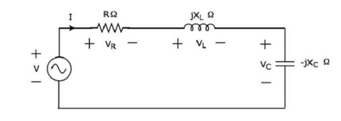
Series RLC Circuit - Consider a series circuit with a resistor (R), an inductor (L), and a capacitor (C), driven by a sinusoidal voltage source
-
Impedances:
- Resistor:
- Inductor:
- Capacitor: =
-
Total Impedance:
-
Phasor Voltage:
-
Voltage Drops across Components:
- Resistor: =
- Inductor: =
- Capacitor: =
Each voltage drop is calculated using phasor multiplication.
-
Time-Domain Current:
Single Phase AC Parallel Circuits
In a parallel AC circuit, all components are connected across the same two points, so they all have the same voltage but different currents.
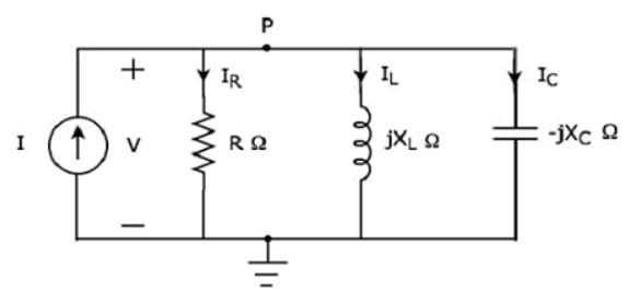
Parallel RLC Circuit:: Consider a parallel circuit with a resistor (R), an inductor (L), and a capacitor (C), driven by a sinusoidal current source
-
Admittances (reciprocal of impedance):
- Resistor: =
- Inductor: = =
- Capacitor: =
-
Total Admittance:
-
Phasor Current:
-
Phasor Voltage:
-
Time-Domain Voltage:
-
Currents through Components:
- Resistor: =
- Inductor: =
- Capacitor: =
Each current is calculated using phasor multiplication.
Numericals
Power Dissipation in AC circuits
Topic asked in Basic Electrical Engg 2023 (CBCS/NEP) question paper Section C - 5.
In AC circuits, power dissipation involves both real power (active power) and reactive power.
Types of Power
-
Real Power (P):
- Also known as active power or true power.
- Measured in watts (W).
- Represents the actual power consumed by resistive components in the circuit.
- Calculated as:
-
Reactive Power (Q):
- Measured in volt-amperes reactive (VAR).
- Represents the power stored and released by reactive components (inductors and capacitors) in the circuit.
- Calculated as:
-
Apparent Power (S):
- Measured in volt-amperes (VA).
- Represents the combination of real and reactive power.
- Apparent power can also be represented in complex form:
- Calculated as:
-
Complex Power:
Complex power (S) in AC circuits is a combination of real power (P) and reactive power (Q):
where:
- is the complex power measured in volt-amperes (VA).
- is the real power measured in watts (W).
- is the reactive power measured in volt-amperes reactive (VAR). The magnitude of the complex power is known as the apparent power:
-
Power Factor (PF):
- The ratio of real power to apparent power.
- =
- Indicates the efficiency of power usage in the circuit.
Numericals
Power Factor Correction
Power Factor Correction is a technique which uses capacitors to reduce the reactive power component of an AC circuit in order to improve its eficiency and reduce current. For an AC circuit, the power dissipated in watts at any instant in time is equal to the product of the volts and amperes at that exact same instant, this is because an AC voltage (and current) is sinusoidal so changes continuously in both magnitude and direction with time at a rate determined by the source frequency.
This process reduces the phase difference between voltage and current, thereby minimizing the reactive power component and improving the efficiency of power usage.
Importance of Power Factor Correction
- Efficiency: Improved power factor means that electrical power is used more efficiently, reducing energy losses.
- Cost Savings: Lower energy losses can lead to reduced electricity bills and lower demand charges from utility companies.
- Increased Capacity: Improved power factor frees up capacity in the electrical system, allowing more equipment to operate without upgrading the infrastructure.
- Reduced Wear and Tear: Reducing the reactive power component decreases the strain on electrical components, leading to longer lifespans for equipment.
Methods of Power Factor Correction
-
Capacitors: Adding capacitors in parallel with inductive loads supplies reactive power locally, reducing the amount of reactive power drawn from the supply.
- Capacitors create a leading current that cancels out the lagging current caused by inductive loads.
-
Synchronous Condensers: These are synchronous motors running without a mechanical load, adjusted to operate at leading power factors.
- Synchronous condensers can provide both leading and lagging reactive power as needed.
-
Static VAR Compensators (SVC): These are advanced devices that can rapidly adjust the amount of reactive power compensation in real-time.
- SVCs use a combination of capacitors and reactors to dynamically control reactive power.
Resonance in Series and Parallel Circuits
Topic asked in Basic Electrical Engg 2023 (CBCS/NEP) question paper Section C - 6.
Resonance in AC circuits occurs when the inductive reactance and capacitive reactance are equal in magnitude but opposite in phase, causing them to cancel each other out.
Series Resonance
In a series RLC circuit, resonance occurs when the inductive reactance equals the capacitive reactance = . This condition minimizes the impedance of the circuit, leading to maximum current flow.
If the resonance occurs in series RLC circuit, then it is called as Series Resonance. Consider the following series RLC circuit, which is represented in phasor domain.
Here, the passive elements such as resistor, inductor and capacitor are connected in series. This entire combination is in series with the input sinusoidal voltage source.
Apply KVL around the loop.
The above equation is in the form of .
Therefore, the impedance Z of series RLC circuit will be,
Resonant Frequency
The frequency at which resonance occurs is called as resonant frequency . In series RLC circuit resonance occurs, when the imaginary term of impedance Z is zero, i.e., the value of should be equal to zero.
Substitute and in the above equation.
Therefore, the resonant frequency of series RLC circuit is,
Where, is the inductance of an inductor and is the capacitance of a capacitor. The resonant frequency of series RLC circuit depends only on the inductance and capacitance But, it is independent of resistance
Impedance
We got the impedance of series RLC circuit as,
Substitute in the above equation,
At resonance, the impedance Z of series RLC circuit is equal to the value of resistance R, ie., Z = R
Current flowing through the Circuit
Substitute in Eq.
Therefore, current flowing through series RLC circuit at resonance is
At resonance, the impedance of series RLC circuit reaches to minimum value. Hence, the maximum current flows through this circuit at resonance.
Voltage across Resistor
The voltage across resistor is,
Substitute the value of in the above equation.
Therefore, the voltage across resistor at resonance is .
Voltage across Inductor
The voltage across inductor is,
Substitute the value of in the above equation.
Therefore, the voltage across inductor at resonance is .
So, the magnitude of voltage across inductor at resonance will be,
Where Q is the Quality factor and its value is equal to
Voltage across Capacitor
The voltage across capacitor is,
Substitute the value of I in the above equation.
Therefore, the voltage across capacitor at resonance is .
So, the magnitude of voltage across capacitor at resonance will be
Where Q is the Quality factor and its value is equal to .
Characteristics of Series Resonance
- Impedance: At resonance, the impedance is purely resistive and equals the resistance R:
- Current: The current is at its maximum value because impedance is minimized: =
- Voltage Across Components: The voltages across the inductor and capacitor can be much higher than the source voltage, though they cancel each other out, making the overall voltage drop equal to the source voltage.
- Phase Angle: The phase angle between the voltage and current is zero, meaning they are in phase.
Parallel Resonance
In a parallel RLC circuit, resonance occurs when the total impedance of the circuit is maximized, which happens when the reactance of the inductor and capacitor cancel each other out.
If the resonance occurs in parallel RLC circuit, then it is called as Parallel Resonance. Consider the following parallel RLC circuit, which is represented in phasor domain.
Here, the passive elements such as resistor, inductor and capacitor are connected in parallel. This entire combination is in parallel with the input sinusoidal current source.
Write nodal equation at node P.
The above equation is in the form of I = VY.
Therefore, the admittance Y of parallel RLC circuit will be,
Resonant Frequency
We know that the resonant frequency, is the frequency at which, resonance occurs. In parallel RLC circuit resonance occurs, when the imaginary term of admittance, Y is zero. i.e., the value of should be equal to zero
The above resonance condition is same as that of series RLC circuit. So, the resonant frequency, will be same in both series RLC circuit and parallel RLC circuit.
Therefore, the resonant frequency, fr of parallel RLC circuit is
Where,
- is the inductance of an inductor.
- is the capacitance of a capacitor.
The resonant frequency, of parallel RLC circuit depends only on the inductance and capacitance But, it is independent of resistance R.
Admittance
We got the admittance of parallel RLC circuit as,
Substitute, in the above equation.
At resonance, the admittance, of parallel RLC circuit is equal to the reciprocal of the resistance, R. i.e., .
Voltage across each Element
Substitute, in Eq.(i)
Therefore, the voltage across all the elements of parallel RLC circuit at resonance is V = IR.
At resonance, the admittance of parallel RLC circuit reaches to minimum value. Hence, maximum voltage is present across each element of this circuit at resonance.
Current flowing through Resistor
The current flowing through resistor is,
Substitute the value of in the above equation.
Therefore, the current flowing through resistor at resonance is .
Current flowing through Inductor
The current flowing through inductor is,
Substitute the value of in the above equation.
Therefore, the current flowing through inductor at resonance is .
So, the magnitude of current flowing through inductor at resonance will be,
Where, is the Quality factor and its value is equal to .
Current flowing through Capacitor
The current flowing through capacitor is,
Substitute the value of in the above equation.
Therefore, the current flowing through capacitor at resonance is
So, the magnitude of current flowing through capacitor at resonance will be,
Where, is the Quality factor and its value is equal to
Characteristics of Parallel Resonance
- Impedance: At resonance, the impedance is at its maximum and is ideally infinite (practically very high).
- Current: The total current from the source is minimized because the circuit draws the least current at resonance.
- Branch Currents: While the total current is minimized, the currents through the inductor and capacitor are equal in magnitude but opposite in phase, leading to circulating currents within the LC branch.
- Phase Angle: The phase angle between the total current and voltage is zero, meaning they are in phase.
Numericals
AC Circuits
Sinusoidal sources and RC, RL and RLC circuits, including series and parallel circuits along with numericals
Three Phase Circuits
Balanced and unbalanced 3-phase circuit - voltage, current and power relations, 3-phase power measurement, Comparison of single phase and three phase supply systems.