Balanced and Unbalanced 3-Phase Circuit - Voltage, Current and Power Relationship
Three-phase circuits are widely used in power systems for their efficiency in delivering power. These circuits can be categorized into balanced and unbalanced circuits based on the equality of the loads connected to each phase.
Balanced Three-Phase Circuits
In a balanced three-phase circuit, the loads connected to each phase are equal in magnitude and phase angle. It leads to several advantageous properties:
-
Equal Phase Voltages and Currents:
- The phase voltages are equal in magnitude and 120 degrees apart.
- The phase currents are equal in magnitude and also 120 degrees apart.
-
No Neutral Current:
- In a balanced system, the sum of the currents in the three phases is zero, resulting in no current flowing through the neutral wire (in a four-wire system).
-
Simplified Calculations:
- Analysis can be done using per-phase equivalent circuits, simplifying calculations.
Star (Wye) Connection
-
Phase voltage () is the voltage across each phase winding.
-
Line voltage () is the voltage between any two lines and is times the phase voltage:
-
Phase current is the current through each phase winding.
-
Line current is equal to the phase current:
Delta Connection
-
Phase voltage () is the voltage across each phase winding and is equal to the line voltage:
-
Phase current () is the current through each phase winding.
-
Line current () is times the phase current:
Voltage Relationships
In a three-phase system, voltages can be measured between the lines (line-to-line voltage) or between each line and the neutral point (line-to-neutral voltage).
- Line-to-Line Voltage (): The voltage measured between any two lines.
- Line-to-Neutral Voltage (): The voltage measured between any line and the neutral point.
The relationship between the line-to-line voltage () and the line-to-neutral voltage () is:
Current Relationships
In a balanced three-phase system, the line current is the current flowing through each of the lines, and the phase current is the current flowing through each load impedance.
- Line Current (): The current flowing in each line conductor.
- Phase Current (): The current flowing through each load impedance.
The line current () is equal to the phase current():
Power Relationships
The power in a balanced three-phase system consists of three components: real power (P), reactive power (Q), and apparent power (S).
- Real Power (P): The actual power consumed by the load, Measured in watts (W).
- Reactive Power (Q): The power stored and released by inductors and capacitors in the system, Measured in volt-amperes reactive (VAR).
- Apparent Power (S): The product of the RMS values of voltage and current, Measured in volt-amperes (VA).
- Power Factor (PF): The ratio of real power to apparent power.
Unbalanced Three-Phase Circuits
An unbalanced three-phase AC circuit occurs when the impedances in the three phases are not equal, leading to unequal phase currents and voltages. This imbalance can result in complications such as neutral current flow, voltage distortion, and potential equipment damage.
Analyzing unbalanced systems can be more complex than balanced systems, often requiring the use of symmetrical components. Characteristics of Unbalanced Systems:
- Unequal Phase Impedances: The loads or impedances connected to each phase are different.
- Non-zero Neutral Current: In a four-wire system, the imbalance causes current to flow through the neutral wire.
- Complex Calculations: Requires simultaneous equations or methods like symmetrical components for analysis.
Star (Wye) Connection
-
Phase voltages and currents will differ from phase to phase.
-
Neutral current will be the sum of the currents in the three phases and can be significant:
-
Line-to-line voltages will not be times the phase voltages and must be calculated individually.
Delta Connection
-
Similar to Star, the phase currents will differ from phase to phase.
-
The imbalance in voltages and currents will result in complex power calculations.
Power Relationships
Power calculations in unbalanced systems are more complicated and generally require the use of symmetrical components or direct phase-by-phase analysis:
-
Active Power : The active power in an unbalanced three-phase circuit can be expressed as:
where:
-
, , and are the phase voltages
-
, , and are the phase currents
-
, , and are the phase angles between the voltages and currents for each phase.
-
-
Reactive Power : The reactive power () in an unbalanced three-phase circuit can be expressed as:
where:
- , , and are the phase voltages
- , , and are the phase currents
- , , and are the phase angles between the voltages and currents for each phase.
-
Apparent Power : The apparent power is given by:
where:
- is the active power
- is the reactive power
3-Phase Power Measurement
Power measurement in an AC circuit is measured with the help of a Wattmeter. A Wattmeter is an instrument which consists of two coils called Current coil and Potential coil. The current coil having low resistance is connected in series with the load so that it carries the load current. The potential coil having the resistance is connected across the load and carries the current proportional to the potential difference.
According to Blondel’s theorem: When power is supplied by the K wire AC system, the number of wattmeters required to measure power is one less than the number of wire i.e. (KI), regardless the load is balanced or unbalanced. Hence, Three wattmeters are required to measure power in three phase, four wire system, whereas, only two wattmeters are required to measure the power in 3 phase, 3 wire system.
Hence, Three wattmeters are required to measure power in three phase, four wire system, whereas, only two wattmeters are required to measure the power in 3 phase, 3 wire system.
Three-Wattmeter Method of Three Phase Power Measurement
Three Wattmeter method is employed to measure power in a 3 phase, 4 wire system. However, this method can also be employed in a 3 phase, 3 wire delta connected load, where power consumed by each load is required to be determined separately. The connections for star connected loads for measuring power by Three wattmeter method is shown below:
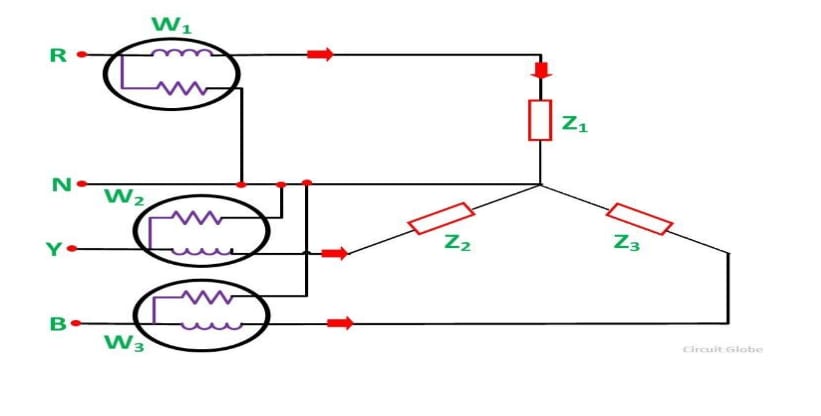
The pressure coil of all the Three wattmeters namely W1, W2 and W3 are connected to a common terminal known as the neutral point. The product of the phase current and line voltage represents as phase power and is recorded by individual wattmeter.
The total power in a Three wattmeter method of power measurement is given by the algebraic sum of the readings of Three wattmeters. i.e.
For each wattmeter:
Where:
- , , and are the power readings of the three wattmeters.
- , , and are the phase voltages.
- , , and are the phase currents.
- , , and are the phase angles between the voltage and current in each phase.
Total Power
Except for 3 phase, 4 wire unbalanced load, 3 phase power can be measured by using only Two Wattmeter Method.
Comparison of Single Phase and Three Phase Supply Systems
Single Phase Supply Systems
A single-phase supply system is a type of electrical power distribution that uses a single alternating current (AC) voltage to supply power to electrical devices and systems.
Key Features::
- Single AC Voltage: The system uses one alternating voltage, which oscillates sinusoidally over time.
- Voltage and Frequency: Common voltage levels are 120V or 230V, and the frequency is typically 50 Hz or 60 Hz, depending on the region.
- Two Wires: The system usually involves two conductors - one live (hot) wire and one neutral wire.
- Sinusoidal Waveform: The voltage alternates in a sinusoidal waveform, going through positive and negative cycles.
In a single-phase system, the voltage alternates between a positive peak and a negative peak. This results in a power delivery that pulsates, meaning there are moments (at zero crossings) where no power is being delivered.
Advantages
- Simplicity: Easier to install and maintain due to fewer components and simpler wiring.
- Cost-Effective: Lower initial and maintenance costs compared to three-phase systems.
- Suitable for Low Power: Adequate for residential and light commercial applications with lower power demands.
Disadvantages
- Pulsating Power: Power delivery is not constant, which can be less efficient and cause fluctuations in power delivery.
- Limited Capacity: Not suitable for high power applications due to higher losses and limited capacity.
- Less Efficient for Motors: Single-phase motors are generally less efficient and have more complex starting mechanisms compared to three-phase motors.
Three Phase Supply Systems
A three-phase supply system is a type of electrical power distribution that utilizes three alternating currents (AC) of the same frequency but with a phase difference of 120 degrees between them.
Key Features::
- Three Phases: The system consists of three AC voltages (phases) that are sinusoidal and evenly spaced in phase by 120 degrees.
- Higher Voltage and Power Capacity: Typically operates at higher voltages such as 400V, 480V, or higher, allowing for greater power delivery.
- Balanced Load Distribution: Each phase carries equal power and current when the load is balanced, resulting in smoother power delivery.
- Continuous Power: Provides a continuous and constant supply of power due to the overlapping nature of the three phases.
In a three-phase system, each phase alternates sinusoidally but with a phase difference of 120 degrees. This ensures that at any given time, at least one phase is generating power, resulting in a smoother and more continuous supply compared to single-phase systems.
Advantages
- Efficiency: More efficient than single-phase systems for high-power applications due to balanced loads and reduced losses.
- Powerful Motors: Suitable for powering large motors and machinery with higher efficiency and smoother operation.
- Cost-Effective: Provides higher power capacity per conductor compared to single-phase systems, reducing overall installation and operating costs.
Disadvantages
- Industrial Settings: Used extensively in manufacturing plants, factories, and industrial facilities to power heavy machinery, pumps, compressors, and other equipment.
- Commercial Buildings: Used in large commercial buildings, offices, and shopping centers for HVAC systems, elevators, and lighting.
- Power Distribution Networks: Essential in utility power distribution networks for efficient transmission and distribution of electricity over long distances.
| Feature | Single-Phase Supply System | Three-Phase Supply System |
|---|---|---|
| Number of Phases | One | Three |
| Phase Difference | N/A | 120 degrees between phases |
| Voltage Levels | Typically 120V or 230V (residential) | Typically 400V, 480V, or higher (industrial) |
| Power Delivery | Pulsating | Continuous and smoother |
| Efficiency | Generally less efficient for high-power loads | More efficient for high-power loads |
| Load Balancing | Not applicable. | Requires balanced load across all three phases. |
| Complexity | Simpler | More complex |
| Availability | Widely available | Less common in residential areas |
| Power Factor | Usually lower unless corrected | Generally better due to balanced loads |
| Usage Examples | Home appliances, small shops | Factories, industrial plants, large buildings |
Phasors
Concept of Phasors, Phasor representation of circuit elements, Complex notation representation, Single phase AC Series and parallel circuits, power dissipation in AC circuits, power factor correction, Resonance in series and parallel circuits
Electromagnetic Induction
Electromagnetic induction, Faraday law of Electromagnetic Induction, Applications of Electromagnetic Induction , Dot convention, Equivalent inductance