Electromangnetic Induction
Electromagnetic induction is the process by which a changing magnetic field within a conductor induces a voltage (electromotive force, EMF) across the conductor. This principle was discovered by Michael Faraday in 1831 and is the fundamental operating principle behind many electrical devices and systems, such as transformers, electric generators, and induction motors.
Faraday law of Electromagnetic Induction
Faraday gave two laws of electromagnetic induction that are called the Faraday law of Electromagnetic Induction that are,
- Faraday's First Law of Electromagnetic Induction
- Faraday's Second Law of Electromagnetic Induction
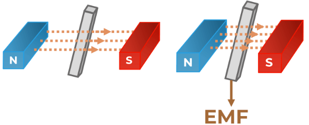
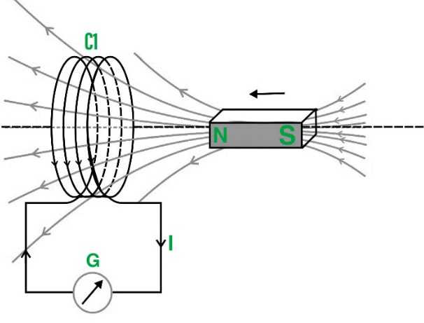
Faraday's First Law of Electromagnetic Induction: When a conductor is put in a changing magnetic field, an induced emf is produced, and if the conductor used is a closed conductor then, an induced current flows through it.
Key Points of Faraday's First Law:
-
Magnetic Field Change: The essential factor for induction is a change in the magnetic field. This change can be caused by moving the conductor within a magnetic field, changing the strength of the magnetic field, or altering the area through which the magnetic field lines pass.
-
Conductor: The presence of a conductive material (such as a wire) is necessary for the induced EMF to result in a current flow.
-
Induced EMF and Current: The induced EMF causes a current to flow if the conductor forms a closed loop. The direction of this current is such that it opposes the change in the magnetic field that produced it, in accordance with Lenz's Law.
Faraday's Second Law of Electromagnetic Induction: Faraday's law states that the induced EMF in a closed circuit is equal to the negative rate of change of the magnetic flux through the circuit.
-
is the induced EMF,
-
is the magnetic flux,
-
is time,
-
is the rate of change of the magnetic flux.
Magnetic Flux : Magnetic flux is the product of the magnetic field (B) and the area (A) through which the field lines pass, and the angle (θ) between the field lines and the perpendicular to the surface.
- is the magnetic field strength,
- is the area through which the magnetic field lines pass,
- is the angle between the magnetic field and the normal to the surface.
Lenz's Law: Lenz's law states that the direction of the induced EMF and the resulting current will be such that it opposes the change in magnetic flux that produced it. This is why the negative sign is present in Faraday's law of induction.
Where,
- is the EMF produced
- is the number of tunrs of the coil Negative Sign indicates that the induced emf opposes the cause of its production.
Eddy Currents: Current loops induced in a conductor when placed in a changing magnetic field are called eddy currents. Eddy currents create a magnetic field that opposes the original magnetic field, which is similar to Lenz's law. These currents are also called Foucault's currents. Eddy currents have very useful applications such as metal detectors, electromagnetic braking, induction heating, etc.
Various applications of the Eddy Currents are:
-
Brakes of Trains: Breaking metal wheels on trains run on metallic tracks and when the brakes are applied, the trains' metal wheels are exposed to a magnetic field, which induces eddy currents in the wheels. As a result of the magnetic interaction between the applied magnetic field and the eddy currents created in the wheels with friction-based braking, the trains slow down.
-
Induction Furnaces: The high temperature in the furnaces is prepared using the concept of eddy current.
Applications of Electromagnetic Induction
- Electromagnetic induction in AC generator
- Electrical Transformers
- Magnetic Flow Meter
- Electromagnetic induction in AC generator: The production of alternating current is one of the most important applications of electromagnetic induction.
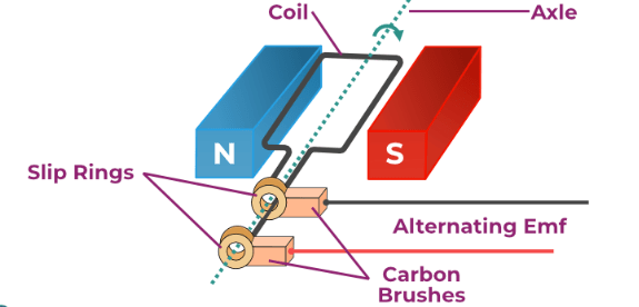
The principle of operation of a basic ac generator is this way of creating a flux change. The axis of the rotating coil is perpendicular to the magnetic field direction. The magnetic flux across the coil changes as the coil rotates, causing an emf to induct in the coil.
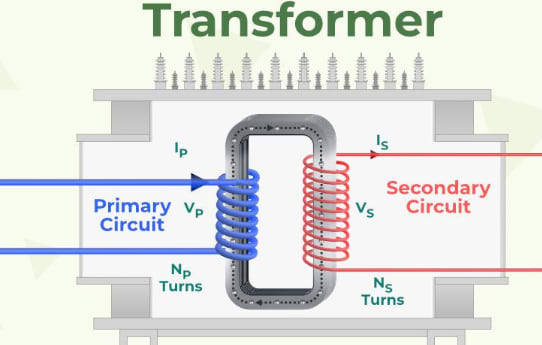
- Electrical Transformers: A transformer is a device that uses a magnetic field to convert ac electric power from one voltage level to another. The voltage in the primary of a step-down transformer is higher than the voltage in the secondary. A step-up transformer is one in which the secondary voltage has additional turns. To increase the voltage to 100 kV, power providers employ a step transformer, which decreases current and reduces power loss in transmission lines. Household circuits, on the other hand, employ step-down transformers to reduce the voltage to 120 or 240 V.
- Magnetic Flow Meter: Magnetic Flow Meter or Electromagnetic Flow Meter is the device used to measure the velocity or volumetric flow of fluids and uses the principle of electromagnetic induction to do so. Magmeter (commonly used term for Magnetic Flow Meter) can only measure the flow of conductive fluids.
Numericals
QUES: A loop of wire is placed in a magnetic field and the magnetic flux through the loop is increasing at a rate of 0.02 if the resistance of the loop of wire is 5 ohms then what is the induced current in the loop?
SOLUTION: For a loop of wire, N=1, and the rate of flux increase is 0.02 i.e., = 0.02 resistance of loop of wire is 5 ohm,
According to Lenz's Law, E =
E = -1×(0.02) = 0.02 Volts
We know Ohm's Law states, V = IR
⇒ I = V/R = 0.02/5 = 0.004 Ampere = 4 milliampere
Thus, the Induced current in the wire loop is 4 milliampere
Dot Convention
The dot convention is a method used in electrical engineering to indicate the relative polarity of the windings in transformers and inductors. This notation is crucial for understanding the phase relationships between currents and voltages in coupled inductors or transformers.
Key Aspects of the Dot Convention in Electromagnetism:
-
Magnetic Flux and Polarity:
-
Dot at the Same End: In a pair of coupled coils (like in a transformer), if the dots are placed at the same end of both coils, a positive current entering the dotted terminal of one coil will induce a positive voltage at the dotted terminal of the other coil. This indicates that the magnetic fields are aiding each other.
-
Dots at Opposite Ends: If the dots are placed at opposite ends, a positive current entering the dotted terminal of one coil will induce a negative voltage at the dotted terminal of the other coil. This indicates that the magnetic fields are opposing each other.
-
-
Mutual Inductance:
- The dot convention helps in determining how the magnetic field generated by one coil affects the other coil. If the mutual inductance is positive (aiding), the dots are aligned; if negative (opposing), the dots are opposite.
Purpose of Dot Convention:
- Polarity Indication: It helps to determine whether the voltages at the terminals of the windings are in phase or 180 degrees out of phase with each other.
- Correct Analysis: Ensures accurate analysis of AC circuits, especially when dealing with coupled inductors and transformers.
Using the Dot Convention in Circuit Analysis:
- Dot Placement: When analyzing circuits, always observe the dot placement to determine the phase relationship.
- In-Phase vs Out-of-Phase: Dots on the same ends indicate in-phase voltages, while dots on opposite ends indicate out-of-phase voltages.
- Current Direction: The direction of current relative to the dots helps determine the induced voltage polarity in coupled windings.
Equivalent Induction
Equivalent inductance refers to the overall inductance of a circuit that contains multiple inductors. The method to calculate equivalent inductance depends on whether the inductors are connected in series or parallel.
Inductors in Series
When inductors are connected in series, the equivalent inductance () is simply the sum of the individual inductances. This is because the same current flows through each inductor, and the total voltage across the inductors is the sum of the individual voltages.
Example:
QUES: If three inductors with inductances = 2H, = 3H, = 4H are connected in series, the equivalent inductance is:
SOLUTION: = 2H + 3H + 4H ⇒ 9H
Inductors in Parallel
When inductors are connected in parallel, the equivalent inductance () is found by taking the reciprocal of the sum of the reciprocals of the individual inductances. This is because the voltage across each inductor is the same, and the total current is the sum of the individual currents.
or Alternatively:
Example:
QUES: If three inductors with inductances = 2H, = 3H, = 4H are connected in series, the equivalent inductance is:
SOLUTION:
Coupled Inductors
When dealing with coupled inductors, mutual inductance (M) must be considered, especially if the magnetic fields of the inductors affect each other. The equivalent inductance can be more complex to calculate in such cases.
Series with Mutual Inductance: If two inductors and are in series with mutual inductance M, the equivalent inductance depends on whether the mutual inductance is aiding or opposing.
-
Aiding Mutual Inductance:
-
Opposing Mutual Inductance:
Numericals on Series with Mutual Inductance
Problem 1: Two inductors, and , have inductances of and . They are coupled with a mutual inductance . Find the equivalent inductance when they are connected in series with aiding mutual inductance.
Solution:
For series-aiding mutual inductance, the equivalent inductance is given by:
Substitute the given values:
Problem 2: Consider two inductors with inductances and . They are coupled with a mutual inductance . Find the equivalent inductance when they are connected in series with opposing mutual inductance.
Solution:
For series-opposing mutual inductance, the equivalent inductance is given by:
Substitute the given values:
Parallel with Mutual Inductance: For parallel inductors with mutual inductance, the equivalent inductance formula is more complex and depends on the mutual coupling coefficient k (Where =
- Formula:
Numericals on Parallel with Mutual Inductance
Problem: Two inductors, and , have inductances and . They are coupled with a mutual inductance . Find the equivalent inductance when they are connected in parallel with aiding mutual inductance.
Solution:
When dealing with coupled inductors in parallel, the calculation involves mutual inductance. For simplicity, assume ideal coupling (perfect coupling) and use the following formula:
Substitute the given values:
Problem: Consider two inductors with inductances and . They are coupled with a mutual inductance . Find the equivalent inductance when they are connected in parallel with opposing mutual inductance.
Solution:
For parallel configurations with opposing mutual inductance, the formula is:
Substitute the given values:
Three Phase Circuits
Balanced and unbalanced 3-phase circuit - voltage, current and power relations, 3-phase power measurement, Comparison of single phase and three phase supply systems.
Magnetic Circuits
Analysis of Magnetic circuits, AC excitation of magnetic circuit, Iron Losses, Fringing and stacking, applications, solenoids and relays