What is Inductor?
An inductor is an inactive element found in most power electronic circuits that stores energy in the form of magnetic energy when electricity is delivered to it. One of an inductor's key qualities is that it hinders or opposes any change in the quantity of current passing through it. Whenever the current across the inductor changes, it either gains or loses charge in order to balance the current running through it. The inductor is also known as a choke, reactor, or simply a coil.
Inductance is directly proportional to the number of turns in the coil. It also depends on other things such as the radius of the coil and the type of material around which the coil is wound.
Inductor is made of a wire whose property is inductance, i.e. it opposes the flow of current. The inductance of the wire increases when the number of turns is increased. Inductance is represented by the alphabet ‘L’ and it is measured in Henry. The formula of Inductance can be given by the ratio of flux and the current in the circuit. It is represented as:
where:
- is the inductance (in henries, H),
- is the magnetic flux (in webers, Wb),
- is the current (in amperes, A).
Inductors have two basic functions:
-
To control signals: Controlling signals is one of the primary functions of an inductor. It is used to handle electric or digital signals to get specific results, like changing frequency and filtering them. The frequency of the current passing in an inductor plays a vital role in controlling the signals within an inductor. It is helpful in blocking AC and allows the DC to pass through it. This is possible because higher frequency symbols are passed easily inside an inductor thus allowing DC currents to pass through them easily..
-
To store energy: In an inductor, the core is used to store energy. Inductors store energy in the form of magnetic fields. Energy storage is the process of adding and maintaining power to a system or gadget for future use. This aids in managing, balancing, and controlling the energy consumption of many systems, including buildings and automobiles..
Inductors in Series
The inductor in Series refers to the network of inductors connected end-to-end so that there is only one path for the flow of electric current. The current flowing in each inductor remains the same but the voltage drop in each inductor is different.
When inductors are put together end-to-end in an electrical circuit, their individual amount of inductance add up to make one total degree of induction. This means that all the inductors connecting together in a series make a stronger impact than any one inductor alone.
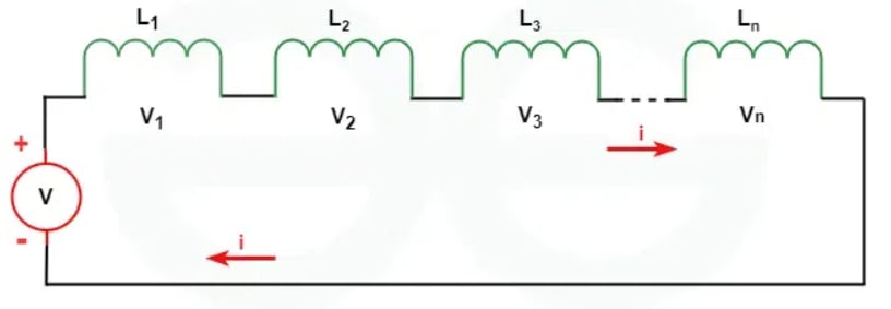
We know that in series the current is equal in each branch. That is,
Total voltage in the circuit is given by:
We know that the formula for voltage across an inductor is given by,
We can write,
But here,
So, the equation reduces to
Hence, the total inductance is given by
Inductors in Parallel
Inductors in parallel are the network of inductors that are connected together with the same two nodes in a circuit. When connected in parallel the voltage across each inductor remains the same, however, the current in each inductor will be different. The maximum opposing inductor will receive the minimum current.
The total inductance of all the inductors connected in parallel will always be less than the individual inductance present in the circuit. The total current in the circuit is the sum of current in each inductor. The total inductance in the circuit increases or decreases according to the amount of magnetic coupling between the coils.
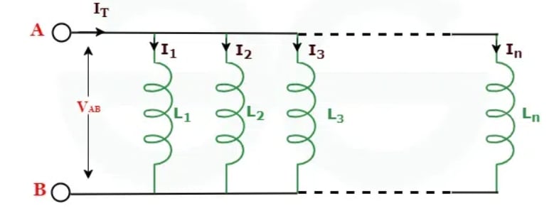
The total current in the circuit is given by:
We know that the formula for voltage across an inductor is given by,
We can write,
Substituting in place of , we get
Therefore, we know , and the equation reduces to
Energy Stored in an Inductor
When electric current flows through an inductor, electrical energy is stored in it. An inductor stores this electrical energy in the form of magnetic energy. The amount of electrical energy an inductor can store depends on its inductance and the magnitude of the electric current flowing through it. The following formula can determine the electrical energy stored by an inductor.
where,
- is Amount of Stored Energy
- is Inductance of Inductor
- is Electric Current Flowing in Inductor
Inductor Energization
When a voltage is applied across an inductor, the current through the inductor does not immediately reach its maximum value. Instead, it increases gradually due to the inductor's property of opposing changes in current. This process is governed by the following key concepts:
- Inductance(L): The property of the inductor that quantifies its opposition to changes in current. It is measured in henries (H).
- Induced EMF: According to Faraday's Law, a changing current through the inductor induces a voltage (EMF) across it, given by:
- Time Constant(τ): For an RL circuit (resistor R and inductor L in series), the time constant is:
- Current Growth: The current I(t) through the inductor as a function of time t when a constant voltage V is applied is given by:
where:
- is the applied voltage,
- is the resistance in the circuit,
- is the time constant
Inductor De-energization
When the voltage across an energized inductor is removed, the current through the inductor does not immediately drop to zero. Instead, it decreases gradually, again due to the inductor's opposition to changes in current. This process involves: Current Decay: The current I(t) through the inductor as a function of time t after the voltage source is removed is given by:
where:
- is the initial current through the inductor at the moment the voltage is removed,
- τ is the time constant
Voltage-Current Relationship for an Inductor
The voltage across an inductor L is directly proportional to the rate of change of current I through it. This relationship can be written as:
where:
- is the voltage across the inductor,
- L is the inductance in henries (H),
- is the rate of change of current through the inductor.
Explanation
-
Inductance (L): Inductance is a measure of an inductor's ability to store energy in its magnetic field and oppose changes in current. It is dependent on the physical characteristics of the inductor, such as the number of turns in the coil, the area of the coil, and the core material.
-
Rate of Change of Current : This term represents how quickly the current through the inductor is changing with respect to time. A rapid change in current induces a larger voltage across the inductor.
Time-Constant
Time constant of the circuit is the time that would be required for the current to drop to zero if it continued to drop at its initial rate. It is designated by Greek letter (tau)
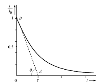
The initial rate of decay is given by the slope of line AB drawn tangential to the curve at starting point B. It is found by evaluating the derivative at zero time,
Thus, from triangle OAB, we have
Since the exponent must be dimensionless, the ratio must have the units of seconds. In terms of time constant , the response of the series circuit may be written simply as
The time constant for an inductor (τ) is defined as the ratio of the inductance (L) to the resistance (R) in an RL (resistor-inductor) circuit. It quantifies how quickly the current through the inductor changes in response to changes in the circuit conditions, particularly when the circuit is energized or de-energized.
Time Constant Formula: In an RL circuit, the time constant τ is given by:
where:
- is the inductance of the inductor in henries (H),
- is the resistance in ohms (Ω).
Understanding the time constant of an inductor is crucial in various applications:
- Transient Response: It helps in predicting how quickly the current in an RL circuit will settle to its final value when a voltage is applied or removed.
- Circuit Design: Designers use the time constant to optimize the performance of circuits involving inductors, such as filters, oscillators, and power supplies.
- Signal Processing: In signal processing applications, the time constant influences the response time of circuits to changes in input signals.
Transient Response of RL, RC and RLC Circuits
Transient Response of RL Circuits
Topic asked in Basic Electrical Engg 2023 (CBCS/NEP) question paper Section B - 4(ii).
The transient response of RL (resistor-inductor) circuits describes how these circuits behave when a sudden change in voltage or current occurs. Understanding this response is crucial for designing and analyzing RL circuits in various applications, including power supplies, motor control circuits, and signal filtering.
RL Circuit Components: An RL circuit consists of:
- : Resistor (in ohms, Ω), which limits the current.
- : Inductor (in henries, H), which stores energy in its magnetic field.
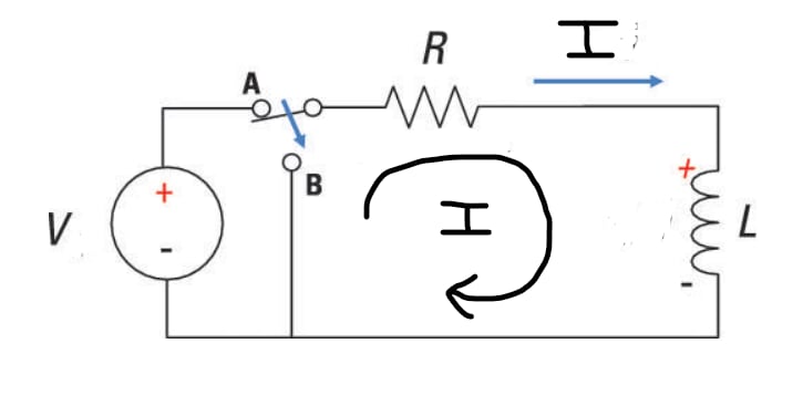
Case-I: t < 0 [Switch at position A]
Once inductor is completely energised it will act as short circuit.
Apply KVL in loop:
Case-II: t = 0 [Switch at position B]
When switch moves to position B, inductor releases its energy.
Apply KVL in loop:
Intergrating Eq.(i) we get,
Therefore,
At t = 0, putting this in Eq.(ii) we get,
Substituting value of K in Eq.(ii),
Therefore Time response of current in RL circuit is given by:
Time Constant (τ): The time constant τ of an RL circuit is given by:
where:
- is the inductance of the inductor.
- is the resistance in the circuit.
The time constant τ determines the rate at which the current through the inductor changes in response to changes in the circuit conditions.
When a sudden change in voltage or current is applied to an RL circuit, the current through the inductor and the voltage across it change over time.
Transient Response of RC Circuits
Topic asked in Basic Electrical Engg 2023 (CBCS/NEP) question paper Section B - 3.
The transient response of RC (resistor-capacitor) circuits describes how these circuits behave when subjected to sudden changes in voltage or current. RC circuits are fundamental in electronics and find applications in signal processing, timing circuits, filters, and many other areas. Understanding their transient response is crucial for designing and analyzing these circuits effectively.
RC Circuit Components:
- : Resistor (in ohms, Ω), which limits the current.
- : Capacitor (in farads, F), which stores and releases electrical energy.
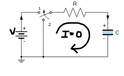
Case-I: t < 0 [Switch at position 1]
Once completely charged capacitor will act as a open circuit.
Case-II: t = 0 [Switch at position 2]
When the capacitor gets discharged, it reverses the direction of current
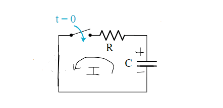
Apply KVL in loop:
Differentiation Eq.(i)
Integrating Eq.(ii), we get,
At t = 0, putting this in Eq.(iii) we get,
Hence,
Therefore Time response of current in RC circuit is given by:
Time Constant (τ): The time constant τ of an RC circuit is defined as:
where:
- is the resistance in the circuit.
- is the capacitance of the capacitor.
The time constant τ dictates how quickly the capacitor charges or discharges through the resistor in response to changes in the circuit conditions.
When a sudden change in voltage or current is applied to an RC circuit, the voltage across the capacitor and the current through the resistor change over time.
Transient response of RLC Circuits
The transient response of RLC (resistor-inductor-capacitor) circuits describes how these circuits behave when subjected to sudden changes in voltage or current. RLC circuits are fundamental in electronics and are used in various applications such as filters, oscillators, and signal processing circuits. Understanding their transient response is crucial for designing and analyzing these circuits effectively.
RLC Circuit Components:
- : Resistor (in ohms, Ω), which limits the current.
- : Inductor (in henries, H), which stores energy in its magnetic field.
- : Capacitor (in farads, F), which stores and releases electrical energy.
Time Constant (τ) and Natural Frequency : The transient response of an RLC circuit is influenced by two key parameters:
- Time Constant (τ):
- The time constant of an RLC circuit depends on the damping factor and is typically defined in terms of the resistance R, inductance L, and capacitance C.
- For an underdamped RLC circuit (where ),the time constant τ is approximately:
- Natural Frequency :
- The natural frequency of oscillation of the RLC circuit is given by:
- In the context of an RLC circuit, ζ (zeta) represents the damping factor. It's a dimensionless quantity that characterizes how the energy in the circuit's oscillations dissipates over time due to the presence of resistance.
The damping factor for a series RLC circuit is calculated as:
- Underdamped : Oscillatory response.
- Critically Damped : Fastest response to steady state without oscillation.
- Overdamped : No oscillation, slower response to steady state.