What is Capacitor?
Topic asked in Basic Electrical Engg 2023 (CBCS/NEP) question paper Section B - 4(i).
Capacitors are essential components in electronics for storing and releasing electrical energy efficiently. They store electrical energy in the form of an electric field.
-
Basic Structure: The basic design of a capacitor involves two conductive plates, often made of metal, with a small distance between them. The space between these plates is filled with a dielectric material. This structure allows the capacitor to store electric charge when a voltage is applied across its terminals.
-
Dielectric: The dielectric material between the plates determines the capacitor's capacitance, which measures its ability to store charge. Common dielectric materials include ceramics, paper, plastic films, and electrolytes in electrolytic capacitors.
-
Capacitance: Capacitance (C) is measured in Farads (F) and depends on the area of the plates, the distance between them, and the type of dielectric material used.
-
Types of Capacitors:
- Electrolytic Capacitors: These capacitors use an electrolyte as the dielectric and are polarized (with positive and negative terminals). They are commonly used in power supply circuits.
- Ceramic Capacitors: These capacitors use ceramic as the dielectric and are non-polarized. They are widely used for decoupling and filtering applications.
- Film Capacitors: These capacitors use thin plastic films such as polyester (Mylar), polypropylene, and PTFE (Teflon) as dielectric materials. They are used in timing circuits, filters, and audio applications.
- Tantalum Capacitors: These capacitors use tantalum metal as the anode with an oxide layer as the dielectric. They offer high capacitance per volume and are used in compact electronic devices.
- Variable Capacitors: These capacitors have a variable capacitance that can be adjusted mechanically or electronically. They are used in tuning circuits and adjustable frequency applications.
How are Capacitors Connected?
Capacitors can be arranged in different configurations, affecting the total capacitance of the circuit. The total capacitance can be defined as the ratio of the total charge to the total voltage applied in the circuit:
where,
- is Capacitance
- is Charge
- is Voltage
Capacitors can be connected in two main configurations:
- Series Combination
- Parallel Combination
Series Combination of Capacitors
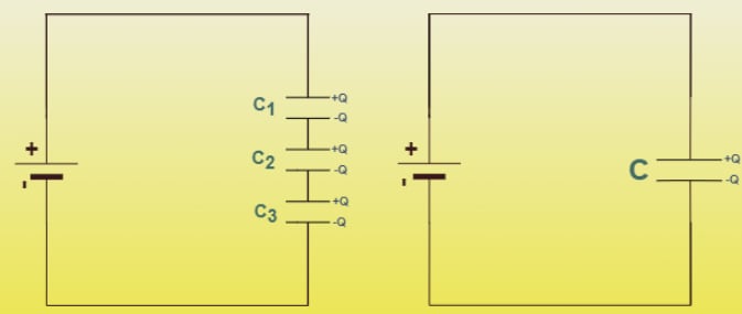
In the figure above, three capacitors are connected in series to a battery of voltage . In a series connection, the same charge accumulates on each capacitor. The total voltage across the combination is the sum of the voltages across each individual capacitor.
Derivation for Series Capacitors:
The Capacitance is given by:
This can be rewritten as,
The voltage across each capacitor is:
The total voltage across the capacitors is:
Substitute the expressions for individual voltages:
Let the equivalent capacitance be ,
Simplify to get:
For capacitors, the relation is:
Example of Capacitor Connected in Series Combination
Given: Four capacitors with capacitances , , , and connected in series then find the equivalent capacitance of the circuit.
The equivalent capacitance is:
Thus, the equivalent capacitance of the capacitor in series is, .
Parallel Combination of Capacitors
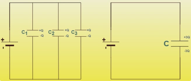
In the figure above, three capacitors , , and are connected in parallel to a voltage source of potential . The voltage across each capacitor is the same as the source voltage. The total charge is the sum of the charges on each capacitor.
Derivation for Parallel Capacitors:
The total charge on the capacitor is:,
Since , we have:
Thus:
For capacitors, the relation is:
Example of Capacitor Connected in Parallel Combination
Given: Four capacitors with capacitances , , , and connected in parallel then find the equivalent capacitance of the circuit.
The equivalent capacitance is:
Thus, the equivalent capacitance of the capacitors in parallel is
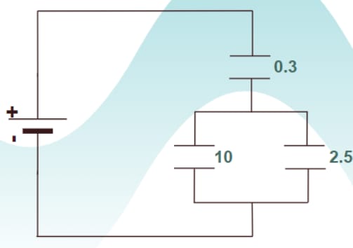
Example on Combination of Capacitors
Example1: Find the equivalent capacitance for the system shown in the figure below.
Formula for Combination of Capacitors in Parallel and Series
-
Parallel:
-
Series:
Given:
For parallel combination:
For series combination:
Thus, the equivalent capacitance of the system is .
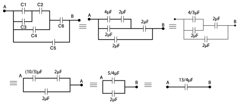
Example2: Find the equivalent capacitance between points A and B. The capacitance of each capacitor is .
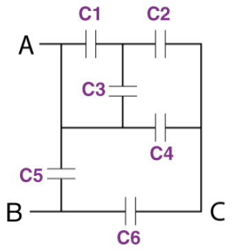
In the system given, 1 and 3 are in parallel. 5 is connected between A and B. So, they can also be represented as follows:
- As 1 and 3 are in parallel, their effective capacitance is
- and are in series, so their effective capacitance is
- and are in parallel, so their effective capacitance is
- and are in series, so their effective capacitance is
- and are in parallel, so their effective capacitance is
Therefore, the equivalent capacitance of the given system is .
Ideal Capacitor
An ideal capacitor, in the realm of electronics, is a theoretical construct used to simplify and understand the fundamental principles of capacitance. It represents the purest form of a capacitor.
Key characteristics of Ideal Capacitor
- The capacitance value remains constant and does not change with applied voltage, frequency, or temperature variations. It is represented by C in Farads (F).
- There is no equivalent series resistance (ESR) present in the ideal capacitor. ESR causes energy loss in real capacitors due to heat dissipation when current flows through them.
- The dielectric material between the capacitor plates is a perfect insulator, allowing no leakage current to flow. Real capacitors have some leakage due to imperfections in the dielectric.
- Ideal capacitors charge and discharge instantaneously in response to changes in applied voltage. There is no delay in this process, simplifying theoretical calculations.
- Ideal capacitors can respond to changes in voltage or current at any frequency, including infinitely high frequencies. This characteristic makes them suitable for applications involving high-frequency signals.
Permittivity
Permittivity is a fundamental property of materials that quantifies their ability to permit the formation of an electric field within them. It is a measure of how easily electric field lines can pass through a material. Permittivity is essential in understanding and designing capacitors and other electrical and electronic systems.
- Permittivity is commonly denoted by the Greek letter epsilon .
- The SI unit of permittivity is farads per meter .
-
Vacuum Permittivity :
- The permittivity of free space (vacuum) is a constant value, denoted by .
- Its approximate value is .
- Vacuum permittivity is a fundamental constant in electromagnetism and appears in equations such as Coulomb's law and the definition of capacitance.
-
Relative Permittivity :
- Relative permittivity, also known as the dielectric constant, is the ratio of the permittivity of a material to the permittivity of a vacuum.
- It is a dimensionless quantity defined as , where ε is the permittivity of the material, and is the vacuum permittivity.
- Different materials have different relative permittivities, which influence their behavior in electric fields.
-
Absolute Permittivity :
- The absolute permittivity of a material is the product of the vacuum permittivity and the relative permittivity: .
- It represents the overall permittivity of the material in a given context.
-
Role in Capacitors: Permittivity is crucial in determining the capacitance of a capacitor. The capacitance (C) of a parallel-plate capacitor is given by:
where:
- is the permittivity of the dielectric material between the plates,
- is the area of one of the plates,
- is the separation between the plates.
- Higher permittivity materials can store more charge for a given voltage, leading to higher capacitance.
The Multi-Plate Capacitor
A multi-plate capacitor is an advanced type of capacitor that consists of multiple parallel conductive plates separated by dielectric materials. The multi-plate configuration increases the overall capacitance without significantly increasing the physical size of the capacitor, making it more efficient and compact for storing electric charge.
- A multi-plate capacitor consists of several parallel plates arranged in such a way that each plate is separated from its adjacent plates by a dielectric material.
- The plates are connected alternately to the two terminals of the capacitor.
Capacitance Calculation:
- For a capacitor with n plates, there are effective capacitors formed between the adjacent plates.
- If each plate has an area A and the separation between the plates is d, and the dielectric material has a permittivity ε, the capacitance of a single capacitor between two plates is given by:
- The total capacitance of the multi-plate capacitor is: This formula accounts for the capacitors in parallel, each contributing to the total capacitance.
Advantages of Multi-Plate Capacitor:
- Increased Capacitance: By using multiple plates, the effective surface area for charge storage increases, leading to higher capacitance.
- Compact Size: Multi-plate capacitors can achieve higher capacitance without a significant increase in size, making them suitable for compact electronic devices.
- Enhanced Performance: The use of multiple plates can also enhance the performance of the capacitor in terms of energy storage and discharge rates.
Example Calculation:
Suppose we have a multi-plate capacitor with 5 plates (forming 4 capacitors in parallel), each with an area of , seprated by dielectric with a permittivity , and a separation distance of 1mm.
The capacitance of each individual capacitor is:
Since there are 4 such capacitors in parallel, the total capacitance is:
Variable Capacitor
A variable capacitor is a type of capacitor whose capacitance can be adjusted or varied. This adjustability makes it highly useful in tuning circuits, such as those found in radios, oscillators, and frequency modulators. Variable capacitors in general consists of interwoven sets of metallic plates in which one is fixed and the other is variable.
These capacitors provide the capacitance values so as to vary between 10 to 500pF. The capacitance of a variable capacitor can be changed by varying the physical characteristics of the capacitor, such as the overlap area of the plates, the distance between the plates, or the dielectric material between the plates.
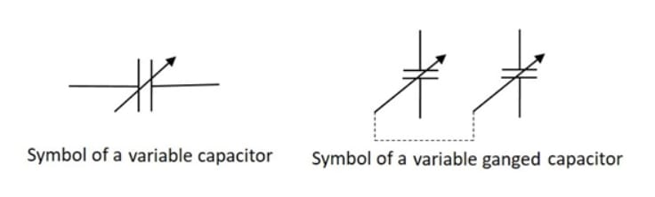
The ganged capacitor shown in above figure is a combination of two capacitors connected together. A single shaft is used to rotate the variable ends of these capacitors which are combined as one. The dotted line indicates that they are connected internally.
The primary feature of a variable capacitor is its ability to change capacitance. This is typically achieved by mechanical means, such as rotating a set of plates to change the overlap area.
Rotary Variable Capacitors: These are the most common type, where a set of rotor plates is interleaved with a set of stator plates. Rotating the rotor changes the overlap area between the rotor and stator plates, thereby adjusting the capacitance.
-
Stator Plates: Fixed plates connected to one terminal.
-
Rotor Plates: Movable plates connected to the other terminal, which can be rotated to change the overlap area with the stator plates.
-
Dielectric: Usually air, but in some designs, a solid dielectric material can be used.
The capacitance C of a variable capacitor can be expressed as:
where:
- is the permittivity of the dielectric material,
- is the overlapping area of the plates,
- is the distance between the plates.
Capacitor Charging and Discharging
Charging of a Capacitor
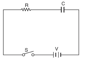
Consider an uncharged capacitor of capacitance farad connected in series with a resistor to a d.c. supply of volts. When the switch is closed, the capacitor starts charging up and charging current flows in the circuit. The charging current is mamimum at the instant of switching and decreases gradually as the voltage across the capacitor increases. When the capacitor is charged to applied voltage , the charging current becomes zero.
-
At Switching instant: At the instant the switch is closed, the voltage across capacitor is zero since we started with an uncharged capacitor. The entire voltage V is droped across resistance R and charging current is maximum ()
- Therefore, Initial charging current,
- Voltage across capacitor = 0
- Charge on Capacitor = 0
-
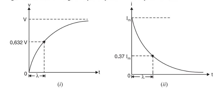
At any instant: After having closed the switch, the charging current starts decreasing and the voltage across capacitor gradually increases.
-
Voltage across the capacitor: The voltage V(t) across the capacitor during charging can be described by the following equation:
Where:
- is the maximum voltage (equal to the supply voltage).
- is the resistance in ohms .
- is the capacitance in farads (F).
- is the time in seconds (s).
- is the base of the natural logarithm (approximately equal to 2.71828).
-
Charge on Capacitor: - = Charge at any time - = final charge since and , Therefore it becomes:
Again the increase in charge on capacitor plates follows exponential law.
-
Discharging of a Capacitor
Consider a capacitor farad charged to p.d.(potential difference) of volts and connected in series with a resistance through a switch . When the switch is open, the voltage across the capacitor is volts. When the switch is closed, the voltage across capacitor starts decreasing. The discharge current rises instantaneously to the value of () and then decays gradually to zero.
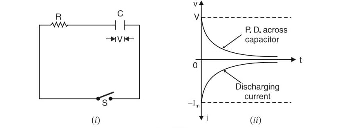
Let at any time during discharging,
- = potential difference across the capacitor
- = discharging current
- = charge on capacitor
By Kirchoff's voltage law, we have,
Integrating both sides, we get,
At the instant of closing the switch, and . Putting these value in eq. (i), we get,
Therefore, Equation(i) becomes:
or,
where, is the time constant and has the dimension of time.
Similarly,
and
Negative sign attached to , shows that the discharging current flows in the opposite direction to that which the charging current flows.
Network Theorems
Superposition theorem , Thevenin's theorem ; Norton's theorem ; Maximum power transfer theorem ; Millman's theorem and Reciprocity theorem
Resistor in DC Circuit
Current-voltage relationship, ohm's law , time-constant, rise-time, fall-time and their mathematical representation in DC Circuit