Current-Voltage Relationship
What is Voltage?
The electrical force that would drive an electric current between two points is termed as voltage. represents voltage.
What is Current?
The rate at which electric charge flows past a point in a circuit is termed as current. represents current.
| Parameters | Voltage | Current |
|---|---|---|
| Definition | Voltage is the potential difference between two points in an electric field, which causes current to flow in the circuit. | Current is the rate of flow of electrons. |
| Unit Charge | ||
| Field Produced | Magnetic Field | Electric Field (Electrostatic) |
| Series Connection | Unequal in all components | Equally distributed in all components |
| Parallel Connection | Magnitude of voltage remains the same in all components | Magnitude of current varies in all components |
| Polarity Changes | Alternating Voltage changes its polarity and magnitude, while it remains constant in DC. | Alternating Current changes its polarity, while Direct Current does not change its polarity. |
| Existence | Voltage can exist without current, as it is the cause of flowing charge. | Current does not exist without voltage, as voltage is the main cause of current flow (except in theoretical superconductors). |
Relationship
The relationship between current and voltage is governed by Ohm's Law, which is fundamental in the field of electrical engineering and physics. Ohm's Law states:
where:
- is the voltage across the conductor (measured in volts, ),
- is the current flowing through the conductor (measured in amperes, ),
- is the resistance of the conductor (measured in ohms, ).
Time-Constant
The time constant is a critical parameter in the analysis of the transient behavior of (resistor-capacitor) and (resistor-inductor) circuits. It provides a measure of how quickly a circuit responds to changes in voltage or current. Her's a detailed look at the time constant for both types of circuits:
RC Circuit Time Constant
For an circuit, which consists of a resistor and a capacitor in series, the time constant is defined as:
where:
- is the resistance in ohms (Ω),
- is the capacitance in farads (F).
Numerical on RC Circuit Time Constant
Question: A resistor of and a capacitor of are connected in series. Calculate the time constant of the circuit.
Given:
Resistance
Capacitance
The time constant is calculated as:
The time constant of the circuit is 0.05 seconds.
RL Circuit Time Constant
For an circuit, which consists of a resistor and an inductor in series, the time constant is defined as:
where:
- is the inductance in henries (H).
- is the resistance in ohms (Ω),
Numerical on RL Circuit Time Constant
Question: An RL circuit has an inductance and a resistance . Calculate the time constant .
Given:
The time constant of the circuit is 0.5 seconds.
Time Constants in RC and RL Circuits
In and circuits, the time constant is a measure of how long it takes for the voltage or current to rise or fall.
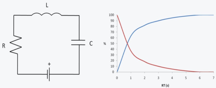
In an circuit, when a voltage is suddenly applied (step input), the capacitor gradually charges up through the resistor, reaching about 63.2% of the applied voltage after one time constant. It will continue to charge until it reaches near 100% of the applied voltage, typically considered fully charged after about 5 time constants (or 5τ).
Conversely, if the voltage source is suddenly removed, the capacitor discharges through the resistor. The voltage across the capacitor decreases over time, dropping to about 36.8% of its original voltage after one time constant. After approximately 5 time constants, the capacitor is considered fully discharged.
In an RL circuit, when a voltage is suddenly applied, the current through the circuit does not immediately reach its maximum value. Instead, it slowly increases and reaches about 63.2% of its maximum value after one time constant. After about 5 time constants, the current is essentially at its maximum value.
If the voltage source is suddenly removed, the current starts to decrease, dropping to about 36.8% of its original value after one time constant. After about 5 time constants, the current is considered to have reached zero.
Steps to calculate time constants in RC and RL circuits:
-
Identify the resistance and either the capacitance for circuits or inductance for circuits. These values are often given in circuit diagrams or can be calculated based on the components used.
-
Use the time constant formulas for RC circuits and for circuits.
-
Plug in the values for , , or , ensuring they are in the correct units (ohms for , farads for , henrys for ).
-
Calculate the time constant, which will be in seconds.
Significance of the Time Constant
The time constant τ is a measure of how quickly the voltage across a capacitor or the current through an inductor reaches its final value after a change. Specifically:
- For an RC circuit, the time constant represents the time it takes for the voltage across the capacitor to reach approximately 63.2% of its final value after a sudden change in voltage.
- For an RL circuit, the time constant represents the time it takes for the current through the inductor to reach approximately 63.2% of its final value after a sudden change in current.
Rise-Time
Rise time measures the time an electrical signal takes to transition from its low state to its high state. Specifically, engineers define rise time as the period required for a signal to go from 10% to 90% of its maximum amplitude.
Rise time is a key parameter in the analysis of transient responses in electrical and electronic circuits, particularly in the context of signals and systems. It is widely used to characterize the speed at which a signal transitions from a low state to a high state.
Definition: Rise time (denoted as ) is defined as the time it takes for a signal to change from a specified low value to a specified high value. In many contexts, it is specifically measured from:
- 10% of the final value to 90% of the final value for analog signals.
- 0% to 100% of the final value for digital signals (although 10% to 90% is often used to avoid measurement noise and overshoot issues).
Mathematical Representation
For a signal V(t), the rise time can be defined as:
where:
- is the time at which the signal reaches 10% of its final value.
- is the time at which the signal reaches 90% of its final value.
Importance of Rise Time
Rise time is an important parameter in various applications:
- Digital Circuits: It determines how fast a digital signal can transition from a low state to a high state, which impacts the maximum operating frequency of digital circuits.
- Analog Circuits: It affects the bandwidth and the ability to accurately reproduce high-frequency components of an input signal.
- Communication Systems: It impacts the data rate and the integrity of transmitted signals, particularly in high-speed communication systems.
Numerical on Rise Time
Question: A digital signal transitions from 0 V to 5 V. The time at 10% of the final value (0.5 V) is 2 ns, and the time at 90% of the final value (4.5 V) is 8 ns. Calculate the rise time.
Given:
The rise time is calculated as:
The rise time is 6 ns.
Fall-Time
Fall time, analogous to rise time, is another key parameter in the analysis of transient responses in electrical and electronic circuits, particularly for signals and systems. It characterizes how quickly a signal transitions from a high state to a low state.
Definition: Fall time(denoted as ) is defined as the time it takes for a signal to change from a specified high value to a specified low value. Typically, it is measured from:
- 90% of the initial value to 10% of the initial value for analog signals.
- 100% to 0% for digital signals (though 90% to 10% is often used to avoid measurement noise and overshoot issues).
Mathematical Representation
For a signal V(t), the fall time can be defined as:
where:
- is the time at which the signal reaches 10% of its initial value.
- is the time at which the signal reaches 90% of its initial value.
Importance of Fall Time
Fall time is important for various applications:
- Digital Circuits: It determines how fast a digital signal can transition from a high state to a low state, impacting the maximum operating frequency and signal integrity.
- Analog Circuits: It affects the ability of the circuit to accurately follow rapid changes in input signals.
- Communication Systems: It influences the data rate and the quality of transmitted signals, particularly in high-speed communication systems.
Numericals on Fall Time
Question: A signal transitions from 10 V to 0 V. The time at 90% of the initial value (9 V) is 5 ns, and the time at 10% of the initial value (1 V) is 15 ns. Calculate the fall time.
Given:
The fall time is calculated as:
The fall time is 10 ns.
Capacitor in DC Circuit
The ideal capacitor, permittivity; the multi- plate capacitor, variable capacitor; capacitor charging and discharging
Inductor in DC Circuit
Inductor energization and de-energization, inductance current-voltage relationship, time-constant; Transient responseof RL, RC and RLC Circuits