Superposition Theorem
It is not a single video but a playlist, and it contains three videos. When one video finishes, the next will play automatically.
The superposition theorem states that the total response (voltage or current) in a linear circuit with multiple sources can be obtained by summing the individual responses caused by each source acting alone while the other sources are turned off.
Mathematically, the superposition theorem can be expressed as follows:
-
Voltage Superposition: The voltage across a component in a circuit is the algebraic sum of the voltages caused by each individual source acting alone, with all other sources turned off. Similarly, the current through a component is the sum of the currents caused by each individual source acting alone.
Where is the total voltage across the component, are the voltages caused by each individual source acting alone, and is the total current through the component, are the currents caused by each individual source acting alone.
-
Current Superposition: The current through a component in a circuit is the algebraic sum of the currents caused by each individual source acting alone, with all other sources turned off. Similarly, the voltage across a component is the sum of the voltages caused by each individual source acting alone.
Where is the total current through the component, are the currents caused by each individual source acting alone, and is the total voltage across the component, are the voltages caused by each individual source acting alone.
The superposition theorem is particularly useful for simplifying circuit analysis in complex circuits with multiple sources. By considering the effects of each source separately, the analysis becomes more manageable and easier to understand. However, it's important to note that the superposition theorem is only applicable to linear circuits, where the response is directly proportional to the input. Nonlinear components like diodes or transistors do not follow the superposition theorem.
Click here to open youtube playlist containing numericals on superposition theorem.
Thevenin's Theorem
It is not a single video but a playlist, and it contains four videos. When one video finishes, the next will play automatically.
Thevenin's theorem states that any linear electrical network with voltage and current sources and resistances can be replaced by an equivalent circuit comprising a single voltage source and a single series resistor. This simplified circuit, known as the Thevenin equivalent circuit.
Thevenin Equivalent Circuit
The Thevenin equivalent circuit consists of the following components:
-
Thevenin Equivalent Voltage : The open-circuit voltage across the terminals of interest when all independent sources within the original circuit are turned off and replaced by their internal resistances. represents the voltage that would be measured across the terminals if connected to an external load or The voltage source present in the Thevenin's equivalent circuit is called as Thevenin's equivalent voltage.
-
Thevenin Equivalent Resistance : The equivalent resistance seen from the terminals of interest when all independent sources within the original circuit are turned off. represents the resistance that the original circuit would present to an external load or the resistance present in the Thevenin's equivalent circuit is called as Thevenin's equivalent resistance.
Click here to open youtube playlist containing numericals on thevenin's theorem.
Thevenin's Theorem Solved Example
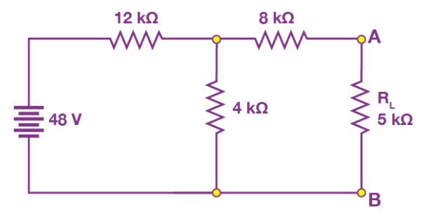
Ques: Find , and the load current flowing through and load voltage across the load resistor in the circuit below using Thevenin's Theorem.
Sol:
Step 1: Remove the 5 kΩ from the circuit.
Step 2: Measure the open-circuit voltage. This will give you the Thevenin's voltage .
Step 3: We calculate Thevenin's voltage by determining the current that flows through 12 kΩ and 4 kΩ resistors.
As both the resistors are in series, the current that flows across them can be calculated as follows:
I = 48 V /( 12 kΩ + 4 kΩ) = 3 mA
The voltage across the 4 kΩ resistors can be calculated as follows:
3 mA x 4 kΩ = 12 V
As there is no current flowing through the 8 kΩ resistor, so there is no voltage drop across it and hence the voltage across the terminals AB is same as the voltage across the 4 kΩ resistor. Therefore, 12 V will appear across the AB terminals. Hence, the Thevenin's voltage, = 12 V.
Step 4: Short the voltage sources as shown in the figure below:
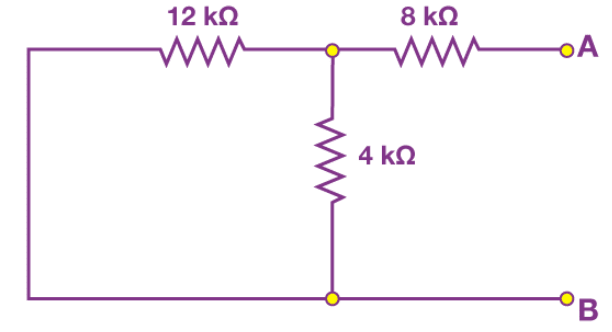
Step 5: Calculate the Thevenin's Resistance
By measuring the open circuit resistance, we can measure Thevenin's resistance.
We notice that the 8 kΩ resistor is in series with the parallel connection of 12 kΩ and 4 kΩ resistors. Therefore, the equivalent resistance or the Thevenin's resistance is calculated as follows:
8kΩ + (4k Ω || 12kΩ)
= 8 kΩ + [(4 kΩ x 12 kΩ) / (4 kΩ + 12 kΩ)]
= 8 kΩ + 3 kΩ
= 11 kΩ
Step 6: Now, connect the in series with Voltage Source and the load resistor as shown in the figure.
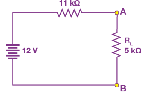
Step 7: For the last step, calculate the load voltage and load current using Ohm's law as follows:
= 12 V / (11 kΩ + 5 kΩ) = 12 V/16 kΩ = 0.75 mA
The load voltage is determined as follows:
= 0.75 mA x 5 kΩ = 3.75 V
Norton's Theorem
It is not a single video but a playlist, and it contains three videos. When one video finishes, the next will play automatically.
Topic asked in Basic Electrical Engg 2023 (CBCS/NEP) question paper Section A - 2.
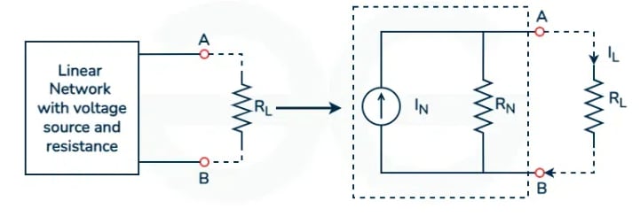
Norton's theorem states that any linear electrical network with voltage and current sources and resistances can be replaced by an equivalent circuit comprising a single current source and a single parallel resistor. This simplified circuit, known as the Norton equivalent circuit.
Norton Equivalent Circuit
The Norton equivalent circuit consists of the following components:
-
Norton Current : The short-circuit current flowing through the terminals of interest when all independent sources within the original circuit are turned off and replaced by their internal resistances. represents the current that would flow through the terminals if a short circuit were connected across them.
-
Norton Resistance : The equivalent resistance seen from the terminals of interest when all independent sources within the original circuit are turned off. represents the resistance that the original circuit would present to an external short circuit across the terminals.
Click here to open youtube playlist containing numericals on norton's theorem.
Norton's Theorem Step-by-Step Procedure:
Here are the steps to be followed for applying Norton's Theorem:
Step 1: Observe all the voltage sources and short them resulting in plain wires. After that observe all the current sources and open-circuit them which will give you all the internal resistances of the circuit.
Step 2: We consider a network shown above to apply Norton's theorem. We will short circuit all the voltages. The circuit after short circuit has been given and we can calculate current IN across the terminals AB
Step 3: Calculating : The whole circuit is replaced by an equivalent resistance RL to replace the short circuit. Now since we replaced the shorted element with Norton's equivalent, the short circuit current ISC will be equal to the Norton current . The formula for calculating the Norton's current has been explained in the later section.
Calculating The final circuit network is displayed in the figure and the left side of terminal AB is replaced by Thevenin's equivalent resistance . Let us see the formula that will be used for calculating the values of , and thevenin voltage. The formula for the Norton's current or short circuit current will be given by
Norton's Theorem Formula
From our previous derivations, we can write down the formula as
and,
Now, we can calculate the short circuit current as
When Norton's theorem is applied to any general circuit, the current source is in parallel with resistance and we can write the current across the load as
Advantages of Norton's Theorem
- Norton's theorem simplifies the overall complexity of the circuit and makes circuit solving an easy process.
- Norton's theorem reduces the size of the circuit by replacing the different current sources with Norton's resistance and Norton's voltage.
- Norton's theorem can be used to find current and voltage across a single element in the network without caring about other elements in a linear circuit.
- Norton's Theorem can be useful for studying the nature of circuits and understanding how internal resistance is dependent on other resistances.
- Norton's Theorem along with Thevenin's theorem is used by engineers to solve complex circuits.
Limitations of Norton's Theorem
- Norton's theorem can only be applied to linear circuit elements and it fails for non linear circuits.
- Circuits that deal with magnetic fields can affect the resistance of the overall circuit so Norton's theorem can't be applied to such magnetic circuits.
- Using Norton's Theorem for the analysis of complex circuits can be a difficult task due to the enumerable mathematical calculations.
- Norton's Theorem is based on certain assumptions which make the results of Norton's Theorem inaccurate in real world due to introduction of real world parameters.
- Norton's Theorem focuses on current carrying elements therefore we have to use Thevenin Theorem to study the voltage distribution.
Norton's Theorem Solved Example
Ques: Solve the value of current and voltage across the load branch in the given circuit using Norton's Theorem.
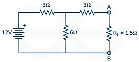
Sol: We will calculate Norton's resistance by shorting the load resistance branch. The circuit will now look like this
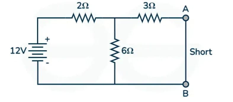
The total resistance for the given circuit is
= 2 + 3 x 6/(3+6)
∴ = 4 ohm
∴ = 4 ohm
We will calculate current using ohm's law
=
∴ = 12/4 = 3A
Using current divider rule, we will calculate the current across the load element
=
∴ = 3 x 6/(3+6)
∴ = 2A
Now we will calculate the Norton's resistance by open circuiting the current sources. The 12 V voltage will become 0 and be replaced by a short. Here is the circuit
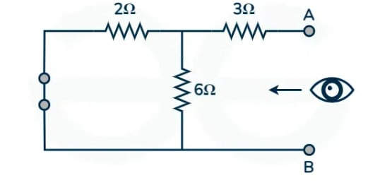
The equivalent voltage will be given by
= 3 + 6 x 2/(2+6)
∴ = 3 + 1.5
∴ = 4.5 ohm
We will calculate thevenin voltage by applying Norton's resistance across the current source. Therefore, using ohms law
= x
∴ = 2A x (4.5Ω /( 4.5Ω + 1.5Ω))
∴ = 1.5A
We can give voltage across load resistance by
= x
∴ = 1.5A x 1.5Ω
∴ = 2.25V
Maximum Power Transfer Theorem
Topic asked in Basic Electrical Engg 2023 (CBCS/NEP) question paper Section E (Compulsory) - 9(b).
The Maximum Power Transfer Theorem states that maximum power is transferred from a source (such as a battery or generator) to a load (such as a resistor) when the impedance of the load is equal to the complex conjugate of the impedance of the source.
This theorem is particularly useful in situations where you want to extract the maximum amount of power from a given source. However, it's important to note that this condition for maximum power transfer does not necessarily yield maximum efficiency. In practical applications, especially in electronic circuits, the goal may be to optimize efficiency rather than maximize power transfer.
The Maximum Power Transfer Theorem is commonly applied in various electrical circuits, including audio amplifiers, power supply design, and transmission lines, to ensure efficient power transfer.
Click here to open youtube playlist containing numericals on maximum power transfer theorem.
Solved Example on Maximum Power Transfer Theorem
Ques: The circuit shown in figure is a model for the common-emitter bipolar junction transistor amplifier. Choose a load resistance so that maximum power is transferred to it.
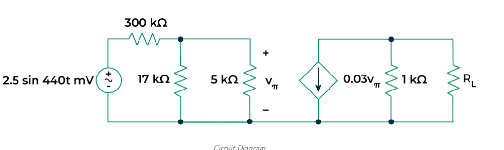
Sol:
Step 1: Find the Thevenin equivalent of the circuit.
To find the , remove and short-circuit the independent sources. The final circuit diagram is shown below:
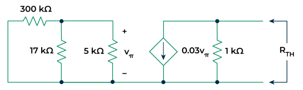
From the above circuit it is clear that = 0. So the dependent current source will behave as an open circuit.
Hence
In order to obtain maximum power delivered into the load, should be set to =1kΩ
Step 2: Find the Thevenin voltage of the circuit.
To find the consider the circuit given below:
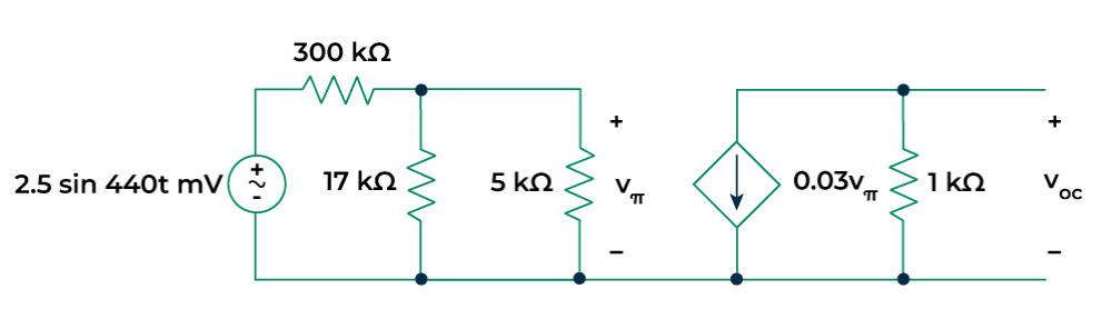
= (1000) =
where the voltage may be found from simple voltage division:
=
=
Step 3: Calculate the Maximum Power Transfer.
=
= μW
Advantages
- It ensures that the maximum available power from a source is efficiently delivered to the load.
- It helps in designing the circuits that minimize power wastage. it leads in making devices more energy-efficient.
- It prevent the overloading of components by matching load resistance with the source resistance which enhance circuit safety.
- It is very easy to apply which helps in quick estimation.
Disadvantages
- It is not applicable in non-linear and unilateral networks.
- Matching resistances may not always be feasible in real-world applications due to component limitations.
- In cases where load resistance doesn't match, it can result in power loss, reducing circuit efficiency.
- The maximum efficiency up to which Maximum Power Transfer Theorem can reach is 50% and not is applicable for power systems.
Millman's Theorem
Millman's Theorem states that the voltage at any point in a network of branches connected in parallel can be calculated by finding the voltage across each branch, multiplying each voltage by the reciprocal of the resistance of that branch, summing these products, and then dividing by the total reciprocal resistance of all branches. This theorem is nothing but a combination of Thevenin's Theorem and Norto's Theorem. It is very useful theorem to find out voltage across the load and current through the load. This theorem is also called as PARALLEL GENERATOR THEOREM.
Mathematically, if a circuit has branches connected in parallel, with voltage sources , , ..., and resistors , , ..., respectively, then the voltage at the common node can be calculated using the following formula:
This theorem is particularly useful for simplifying complex circuits into equivalent circuits, especially when analyzing circuits with multiple voltage sources. It allows engineers to easily determine the voltage at a common node without having to perform detailed node analysis.
For eg:-
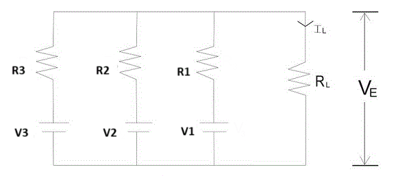
Here , and are voltages of respectively 1st, 2nd and 3rd branch and , and are their respective resistances. , and are load current, load resistance and terminal voltage respectively. Now this complex circuit can be reduced easily to a single equivalent voltage source with a series resistance with the help of Millman's Theorem as shown in figure:-
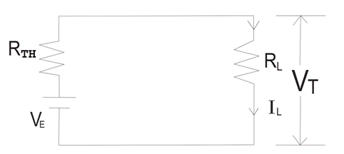
The value of equivalent voltage is specified as per Millman's theorem will be -
This is nothing but Thevenin voltage and Thevenin resistance can be determined as per convention by shorting the voltage source. So will be obtained as
Now load current and terminal voltage can be easily found by -
Click here to open youtube playlist containing numericals on Millman's Theorem.
Reciprocity Theorem
Reciprocity Theorem states that - In any branch of a network or circuit, the current due to a single source of voltage in the network is equal to the current through that branch in which the source was originally placed when the source is again put in the branch in which the current was originally obtained.
In simple words, we can state the reciprocity theorem as when the places of voltage and current source in any network are interchanged the amount or magnitude of current and voltage flowing in the circuit remains the same.
This theorem is used for solving many DC and AC network which have many applications in electromagnetism electronics. These circuits do not have any time-varying element.
Explanation of Reciprocity Theorem
The location of the voltage source and the current source may be interchanged without a change in current. However, the polarity of the voltage source should be identical with the direction of the branch current in each position. The Reciprocity Theorem is explained with the help of the circuit diagram shown below
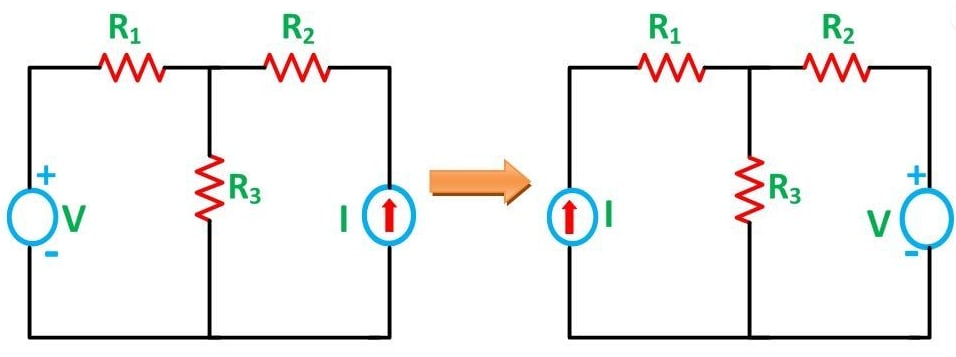
The various resistances , , is connected in the circuit diagram above with a voltage source and a current source . It is clear from the figure above that the voltage source and current sources are interchanged for solving the network with the help of Reciprocity Theorem.
The limitation of this theorem is that it is applicable only to single-source networks and not in the multi-source network. The network where reciprocity theorem is applied should be linear and consist of resistors, inductors, capacitors and coupled circuits. The circuit should not have any time-varying elements.
Steps for Solving a Network Utilizing Reciprocity Theorem:-
-
Step 1 - Firstly, select the branches between which reciprocity has to be established.
-
Step 2 - The current in the branch is obtained using any conventional network analysis method.
-
Step 3 - The voltage source is interchanged between the branch which is selected.
-
Step 4 - The current in the branch where the voltage source was existing earlier is calculated.
-
Step 5 - Now, it is seen that the current obtained in the previous connection, i.e., in step 2 and the current which is calculated when the source is interchanged, i.e., in step 4 are identical to each other.
Click here to open youtube playlist containing numericals on Reciprocity Theorem.