Transformer
It is not a single video but a playlist, and it contains sixteen videos. When one video finishes, the next will play automatically.
A transformer is a static electrical device that transmits AC power from one circuit to another at a constant frequency, but the voltage level may be changed, implying the voltage can be increased or decreased depending on the requirement.
Types of Trannsformers
- Transformer types based on Voltage Level.
- Transformer types based on Core Material.
- Transformer types based on Phases.
- Transformer types based on Construction.
Transformer Types Based on Voltage Level
-
Step-down Transformer: The primary voltage is converted to a lower voltage across the secondary output using a step-down transformer. The number of windings on the primary side of a step-down transformer is more than on the secondary side. As a result, the overall secondary-to-primary winding ratio will always be less than one. Step-down transformer are used in electrical systems that distribute electricity over long distances and operate at extremely high voltages to ensure minimum loss and economical solutions. Step-down transformer are used to change high-voltage into low-voltage supply lines.

-
Step-up Transformer: The secondary voltage of a step-up transformer is raised from the low primary voltage. Because the primary winding has fewer turns than the secondary winding in this sort of transformer, the ratio of the primary to secondary winding will be greater than one. Step-up transformer are frequently used in electronics stabilizers, inverters, and other devices that convert low voltage to a significantly higher voltage. A step-up transformer is also used in the distribution of electrical power. For applications connected to power distribution, high voltage is necessary. In the grid, a step-up transformer is used to raise the voltage level prior to distribution.

Transformer Types Based on Core Material
-
Iron Core Transformer: Multiple soft iron plates are used as the core of an iron core transformer. The iron’s strong magnetic properties of the iron core transformer have extremely high flux linkage. As a result, the iron core transformer has high efficiency. The soft iron core plates come in a variety of sizes and shapes. A few typical shapes include E, I, U, and L.

-
Ferrite core transformer: is a type of transformer that uses a core made of ferrite material, which is a ceramic compound consisting of iron oxide mixed with other metallic elements. Ferrite cores are known for their high magnetic permeability and low electrical conductivity, making them highly efficient at high frequencies.
Transformer Types Based on Phases
-
Single-phase Transformer: is an essential electrical device used in power systems for stepping up (increasing) or stepping down (decreasing) voltage levels in single-phase AC circuits. It operates on the principle of electromagnetic induction and consists primarily of two windings and a magnetic core.

-
Three-Phase Transformer: is a type of transformer designed to convert three-phase electrical power at one voltage level to three-phase power at another voltage level. Three-phase transformers are essential components in power distribution and transmission systems due to their efficiency and ability to handle high power loads.

Transformer Types Based on Construction
-
Core type Transformer: is a type of transformer where the windings surround a significant portion of the core. The core is typically constructed of laminated silicon steel to minimize eddy current losses. In a core type transformer, the magnetic flux path is mostly confined within the core, making it suitable for high voltage applications.

-
Shell type Transformer: is a type of transformer where the core surrounds a significant portion of the windings. The core is usually made of laminated silicon steel to reduce eddy current losses. In a shell type transformer, the magnetic flux is divided and flows through multiple paths, making it suitable for low voltage, high current applications.

Constructional Features of Transformer
-
Core: the core is usually made of laminated silicon steel to reduce eddy current losses. Laminations are insulated from each other to minimize eddy currents and heat generation. Provides a path for the magnetic flux, enabling efficient energy transfer between windings.
-
Windings: It is Made of copper or aluminum wire, these windings are where the input and output electrical energy is transferred. The ratio of turns between primary and secondary windings determines the voltage transformation. Windings are insulated to prevent short circuits. Common insulation materials include enamel, varnish, and paper.
-
Insulation: Laminations are coated to prevent electrical short circuits. Additional layers of insulation are provided between windings and between the windings and core to ensure electrical isolation and safety.
-
Cooling System: Many transformers are immersed in mineral oil, which serves as an insulator and coolant. External radiators or fins attached to the tank help dissipate heat. High-power transformers may use forced air or water cooling systems to enhance heat dissipation.
-
Tank: The transformer tank houses the core and windings. It is made of steel and designed to be robust and durable. The tank is sealed to prevent the entry of moisture and contaminants, and to retain the insulating oil.
-
Bushings: Bushings provide insulated terminals for high voltage connections to the windings. Made of porcelain, resin, or other insulating materials to ensure safe passage of conductors through the transformer tank.
-
Conservator: A conservator tank is used in oil-filled transformers to accommodate the expansion and contraction of insulating oil due to temperature changes. Equipped with a breather containing silica gel to remove moisture from the air entering the conservator.
-
Protection and Monitoring Devices: A gas-actuated relay used in oil-filled transformers to detect faults within the transformer. Monitor the temperature of the transformer windings and oil to prevent overheating. Pressure Relief Devices: Release excessive pressure buildup within the transformer tank.
-
Core Clamping and Frame: Core clamping arrangements hold the core laminations tightly together to minimize vibrations and noise. Provides structural support to the core and windings, ensuring mechanical stability.
-
Magnetic Shielding: Reduces external magnetic fields to prevent interference with nearby electrical equipment. Shielding can be provided by additional laminations or special metallic screens.
-
Grounding: Ensures safety by providing a path for fault currents to the ground. Grounding connections are provided for the core, tank, and other conductive parts.
Operating Principle
A single-phase transformer operates on the principle of electromagnetic induction, which allows it to transfer electrical energy between two or more circuits.
Electromagnetic Induction
The operation of a single-phase transformer is based on Faraday’s Law of Electromagnetic Induction and Lenz's Law:
- Faraday’s Law: The induced electromotive force (EMF) in any closed circuit is equal to the negative of the time rate of change of the magnetic flux through the circuit.
- Lenz’s Law: The direction of the induced EMF and hence the induced current in a closed loop is such that it opposes the change in magnetic flux that produces it.
Operational Steps
-
Applying AC Voltage: An alternating current (AC) voltage is applied to the primary winding. This alternating voltage creates an alternating current in the primary winding.
-
Creating Magnetic Flux: The alternating current in the primary winding generates a time-varying magnetic flux ϕ in the core. This magnetic flux links both the primary and secondary windings.
-
Inducing EMF in Primary Winding: According to Faraday’s Law, the changing magnetic flux induces an electromotive force (EMF) in the primary winding. This induced EMF opposes the applied voltage (Lenz’s Law).
-
Inducing EMF in Secondary Winding: The same changing magnetic flux ϕ also links with the secondary winding, inducing an EMF in the secondary winding. The magnitude of the induced EMF in the secondary winding depends on the number of turns in the secondary winding.
Voltage Transformation
The relationship between the primary and secondary voltages and the number of turns in the windings is given by:
=
where,
- is the primary voltage.
- is the secondary voltage.
- is the number of turns in the primary winding.
- is the number of turns in the secondary winding.
Current Transformation
The relationship between the primary and secondary currents is given by:
=
where,
- is the secondary current.
- is the primary current.
- is the number of turns in the primary winding.
- is the number of turns in the secondary winding.
Power Conservation
In an ideal transformer, the power is conserved (neglecting losses):
=
where,
- is the power input to the primary winding.
- is the power output from the secondary winding
EMF equation of a Single Phase Transformer
Topic asked in Basic Electrical Engg 2023 (CBCS/NEP) question paper Section D - 7(i).
Consider a sinusoidally varying voltage applied to the primary of the transformer shown in Fig.
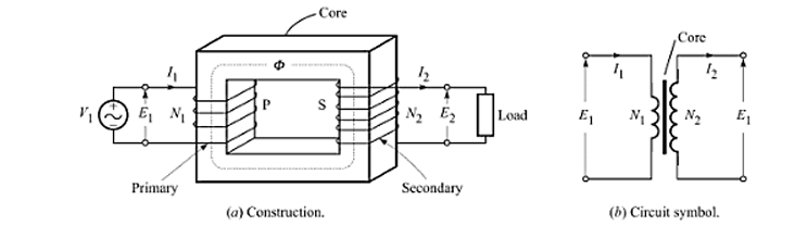
Due to this voltage, a sinusoidally varying magnetic flux is set up in the core, which can be represented as
where is the peak value of the flux and is the frequency of sinusoidal variation of flux. As per the law of electromagnetic induction, the induced emf in a winding of turns is given as
Thus, the peak value of the induced emf is . Therefore, the rms value of the induced emf is given as
or
This equation, known as emf equation of transformer, can be used to find the emf induced in any winding (primary or secondary) linking with flux .
Application of Single-Phase Transformer
- Power Distribution: Single-phase transformers step down high-voltage electricity from the distribution grid to lower voltages suitable for home use These transformers are used to provide power to small businesses and commercial spaces that do not require three-phase power.
- Voltage Regulation: Single-phase transformers can be used in voltage regulation applications to maintain a constant voltage level in power distribution systems. Used in voltage stabilizers to protect electrical appliances from voltage fluctuations by ensuring a steady output voltage.
- Industrial Applications: Single-phase transformers are used in control circuits for machinery and industrial equipment to provide the necessary control voltages. Used in industrial and commercial lighting systems, particularly in applications requiring stable and isolated power supplies for lighting fixtures.
- Portable Power Supplies: Single-phase transformers are integral components in UPS systems, providing backup power and voltage regulation during power outages. Used in portable and standby generators to provide the necessary voltage levels for powering tools, appliances, and temporary electrical setups.
- Renewable Energy: Single-phase transformers are used in smaller solar power installations to step up or step down the voltage from solar panels to match the grid or battery storage systems. Employed in small wind energy systems to convert generated electricity to appropriate voltage levels for storage or grid connection.
Equivalent Circuit
The equivalent circuit of a single-phase transformer helps in analyzing its performance and understanding the internal phenomena that occur during operation. The equivalent circuit can be divided into two parts: the primary side and the secondary side. Key elements include the winding resistances, leakage reactances, magnetizing reactance, and core loss resistance.
- Primary Winding Resistance (): Represents the resistance of the primary winding.
- Primary Leakage Reactance (): Represents the leakage inductance of the primary winding.
- Secondary Winding Resistance (): Represents the resistance of the secondary winding, referred to the primary side.
- Secondary Leakage Reactance (): Represents the leakage inductance of the secondary winding, referred to the primary side.
- Magnetizing Reactance (): Represents the reactance due to the magnetizing inductance of the core.
- Core Loss Resistance (): Represents the core losses due to hysteresis and eddy currents.
Steps to Create the Equivalent Circuit
-
Primary Impedance: Combine the primary winding resistance and the primary leakage reactance (X_1).
= + j
-
Secondary Impedance: Reflect the secondary impedance back to the primary side using the turns ratio (a). Secondary winding resistance referred to the primary side:
=
Secondary leakage reactance referred to the primary side:
=
= +
-
Core Impedance: The magnetizing reactance and core loss resistance are in parallel.
= ||
-
Total Equivalent Impedance: Combine all impedances to form the total equivalent circuit.
Transformer Equivalent Resistance
Transformer equivalent resistance involves converting the resistances from one side (primary or secondary) of the transformer to the other side, making it possible to analyze the entire transformer circuit from one perspective. This is done using the turns ratio of the transformer.
Turns Ratio
The turns ratio of a transformer is the ratio of the number of turns in the secondary winding to the number of turns in the primary winding
Equivalent Resistance
The equivalent resistance transformation can be derived as follows:
Equivalent Primary Resistance in Terms of Secondary
To refer the primary resistance to the secondary side, multiply by the square of the turns ratio :
Equivalent Secondary Resistance in Terms of Primary
To refer the secondary resistance to the primary side, divide by the square of the turns ratio :
Total Resistance of the Transformer in Terms of the Primary
The total resistance in terms of the primary side is the sum of the primary resistance and the equivalent secondary resistance referred to the primary:
Total Resistance of the Transformer in Terms of the Secondary
The total resistance in terms of the secondary side is the sum of the secondary resistance and the equivalent primary resistance referred to the secondary:
Ques. Consider a transformer with a primary winding resistance and a secondary winding resistance . The transformer has a turns ratio of (i.e., ).
- Calculate the equivalent resistance on the secondary side corresponding to the primary winding resistance.
- Calculate the equivalent resistance on the primary side corresponding to the secondary winding resistance.
- Determine the total resistance seen by the primary side of the transformer.
- Determine the total resistance seen by the secondary side of the transformer.
Sol.
-
Equivalent Resistance on the Secondary Side:
The equivalent resistance on the secondary side corresponding to the primary winding resistance is given by:
Substituting the given values:
-
Equivalent Resistance on the Primary Side:
The equivalent resistance on the primary side corresponding to the secondary winding resistance is given by:
Substituting the given values:
-
Total Resistance Seen by the Primary Side:
The total resistance seen by the primary side is:
Substituting the calculated value:
-
Total Resistance Seen by the Secondary Side:
The total resistance seen by the secondary side is:
Substituting the calculated value:
Calculations of Performance Indices
Calculating performance indices for single-phase transformers involves evaluating various parameters to determine the efficiency, voltage regulation, and overall performance.
-
Efficiency (η): Efficiency is the ratio of the output power to the input power, expressed as a percentage. It indicates how well the transformer converts input power into output power with minimal losses.
=
Where:
- is the output power (in watts, W).
- is the input power (in watts, W).
-
Voltage Regulation (VR): Voltage regulation measures the change in secondary voltage from no-load to full-load conditions and is expressed as a percentage.
V R =
Where:
- is the no-load secondary voltage.
- is the full-load secondary voltage.
-
Power Factor (PF): Power factor is the ratio of real power to apparent power and indicates the phase difference between voltage and current.
Where:
- ϕ is the phase angle between the voltage and the current.
-
Losses: Transformers have two main types of losses:
-
Copper Losses:
=
where:
- is the primary current.
- is the secondary current.
- is the resistance of the primary winding.
- is the resistance of the secondary winding.
-
Core Losses: Core losses are typically given by the manufacturer and include hysteresis and eddy current losses.
-