DC Motor Operating Principle
DC Motor is an electrical machine which, when provided with direct current electrical energy, converts it into mechanical energy. It is based on electromagnetic induction, where a conductor carrying current (normally a coil of wire) placed in a magnetic field experiences force to rotate. This rotation is used to perform mechanical work.
DC motor, also known as a direct current motor, is an electric motor that converts mechanical energy from the electrical energy of direct current.
DC Motor Working Principle
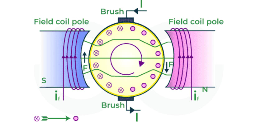
When a current carrying conductor is placed in a magnetic field, a mechanical force acts on it, which can be determined by Fleming’s left hand rule. Due to this force the conductor becomes mobile in the direction of the force.
-
Imagine that a current-free conductor (which is not connected to the supply) is placed in the main magnetic field the and without the magnetic field flowing through the conductor. Assume, there is an air gap from N pole to S pole.
-
Current is flowing in the conductor but the magnetic effect of N pole and S pole has been removed. In this situation the conductor will maintain its own magnetic field. The magnetic field lines of force of the conductor will be clockwise according to the cork screw rule.
-
Current is flowing in the conductor and main magnetic field is also present. The magnetic field produced due to the current in the conductor acts along with the main field above the conductor but opposes the main field below the conductor. The result is that flux accumulates in the region above the conductor and flux density reduces in the region below.
-
From this it is clear that when the force is acting on the conductor, it works to push the conductor downwards. If the direction of current in the conductor is changed, the flux will accumulate downwards and will try to move the conductor upwards.
DC Motor Characteristics
-
Lorentz Force:
If length of conductor = L meter, field intensity = B weber per square meter and current flowing in the conductor = i ampere, then the force experienced by the conductor will be Newton.
where,
- B = flux density (in Tesla).
- L = length of conductor (in meters).
- I = current flowing in the conductor.
- Sinθ = angle between the conductor and magnetic lines of force.
-
DC Motor Torque Formula (τ):
Torque, also known as moment or moment of force, is the force that tends to rotate or move an object around a central axis. A force is a push or pull, similarly, torque creates twisting to an object. Mathematically, torque is given as . For DC Motor, the torque is given as
where,
- is a constant depending on the motor construction.
- is the magnetic flux.
- is the armature current.
-
DC Motor EMF Equation:
EMF or the electromotive force is responsible for flow of current in the electrical appliances. EMF is not an force but the electric potential. In case of DC Motor, a back EMF is produced which counters the armature current. The direction of this back EMF is given by Lenz Law. The formula of back emf is given as
=
where,
- k_e is a constant depending on the motor construction.
- Φ is the magnetic flux.
- ω is the angular speed of the motor.
Construction
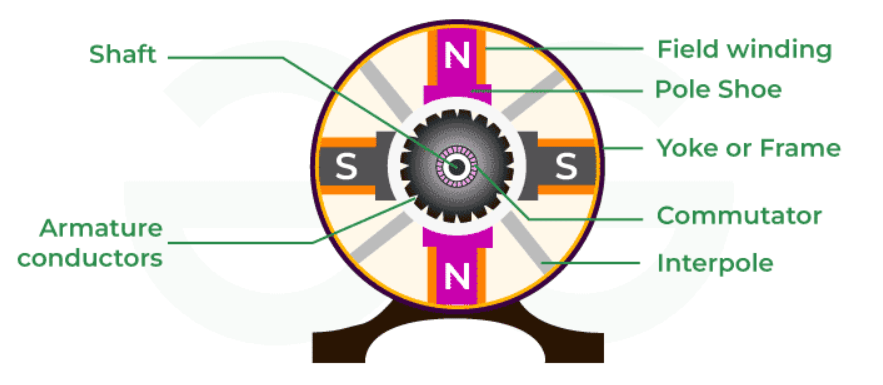
DC motor has such basic components, as a stator (stationary part of the element producing magnetic field) and a rotor part that rotates carrying winding or coil. When a DC voltage is connected to the coil, current flows through it and generates an electromagnetic field. When the magnetic field of this rotor interacts with that produced by the stator, a torque is induced which causes this piece to start spinning.
DC Motor Parts
DC machine has the following main parts:
- Field System or Stator
- Armature
- Commutator
- Brushes
-
Field Coil or Stator: The field coil or stator is the non moving or the stationary part of the DC motor around which coil is wounded and produce magnetic field The stator consists of various parts:
- Yoke
- Pole Core
- Pole Body
- Shoe for the pole
- Field Winding
- End Plates
Yoke: The structure of a DC machine works to create the magnetic circuit between the poles.
Pole Core: Pole Core is usually of laminated iron or other magnetic material. Its function is to serve as a passage for the magnetic flux generated by the field winding.
Pole Body: Pole body works with the pole core. When an electric current passes through the field winding, a magnetic flux is established not only in the pole core but also around it. The poles and their bearings are known as the pole body.
Shoe: Shoe is a synonym for one of the brushes inside an electric motor. DC motors have brushes to make contact with the rotating armature, and typically they are sodded.
Field Winding: Field winding is on the pole core next to the stator. Field winding uses insulated copper wire. An insulated copper coil is wound round the pole core. If this coil on the pole core is excited with direct current, we get magnetic flux.
End Plates: End plates encapsulate the entire motor. They provide a casing for all of the internal parts–the armature, commutator and brushes as well sometimes also including field windings
-
Armature: Armature is the rotating part of the motor which generates mechanical energy. Armature core has windings. The armature core is made of 0.3 to 0.5 mm thick high magnetic strength (silicon steel lamination) and a thin layer of varnish is applied on each sheet.
-
Commutator: Commutators are used in DC appliances such as DC Motors and DC Generators. It periodically reverses the current between the armature and the circuit and produces steady torque
-
Brushes: Brushes or often called Carbon Brushes are made up of graphite. In DC Motors, brushes supplies current to the winding of the armature.
Types of DC Motors
DC Motors can be classified into various categories based on the application and winding connections. Based on the winding of armature DC Motor is of two types
- Self Excited DC Motors
- Separately Excited DC Motors
-
Self Excited DC Motor: DC motors that excite themselves have a part and coil of field connected in series or partly so, same for parallel connection. They can also have combination of series and Parallel connections. They also get power from only one place. Three types of self-excited DC motors exist:
- Series DC motor
- Shunt DC motor
- Compound DC Motor
Series DC Motor: It is a motor in which the field is in series with the armature and its starting torque is very high. This means that the same flow of current goes through both the coil and armature. Series motors always go in one direction and their speed is affected by the physical load.
Shunt DC Motor: Shunt motor is a DC motor in which the field is jointed in parallel to the armature and its starting torque is less than that of series motor. Inside the shunt motor the field winding is connected parallel to the armature winding. The field winding is made of more turns of thin wire. Shunt motors are used in applications where continuous speed is required.
Compound DC Motor: Compound Motor is a Motor in which both series and parallel fields are added. Compound DC motors use both parallel and connected field windings. In the armature winding, everything is in series. However, field coils can be shunt or series types.
-
Separately Excited DC Motor: In DC motors with a separate excite, field coil to make permanent magnets. But, the armature and field coils are not connected electrically to each other. They work separately and do not bother the other. But, the result of the engine is added up with both.
Energy Transfer
The energy transfer in a DC motor involves the conversion of electrical energy into mechanical energy. This process can be broken down into several stages, from the input electrical power to the output mechanical power, while accounting for various losses that occur within the motor.
-
Electrical Input Power: The electrical power input to a DC motor is supplied by a DC voltage source connected to the armature winding. The input power is given by:
Where:
- is the input voltage.
- is the input current.
-
Power in the Armature Circuit: The input electrical power is used to overcome the resistance of the armature winding and generate the back electromotive force (EMF) The power dissipated as heat due to the armature resistance is known as copper losses
Where:
- is the resistance of the armature winding.
- is the armature current.
-
Back EMF and Mechanical Power: EMF or the electromotive force is responsible for flow of current in the electrical appliances. EMF is not an force but the electric potential. In case of DC Motor, a back EMF is produced which counters the armature current. The direction of this back EMF is given by Lenz Law. The formula of back emf is given as
=
where,
- is a constant depending on the motor construction.
- Φ is the magnetic flux.
- ω is the angular speed of the motor.
-
Mechanical Power and Losses: The mechanical power developed by the armature is converted into useful work and mechanical losses. Mechanical losses include friction and windage losses. The useful mechanical power is given by:
Where includes losses due to friction in bearings, windage, and other mechanical losses.
-
Core Losses: Core losses (or iron losses) occur due to hysteresis and eddy currents in the motor’s magnetic core.
-
Efficiency (η): Efficiency is the ratio of the output power to the input power, expressed as a percentage. The efficiency (η) of the DC motor is the ratio of the useful output mechanical power to the input electrical power:
=
Where:
- is the output power (in watts, W).
- is the input power (in watts, W).
Torque Developed by a DC Motor
Topic asked in Basic Electrical Engg 2023 (CBCS/NEP) question paper Section D - 8 (i),(ii).
The voltage equation for a DC motor is:
where,
- is the applied voltage.
- is the back electromotive force (EMF).
- is the armature current.
- is the armature resistance.
If we multiply each term of Eq. () by , the total armature current, we get
Here, represents the total electric power supplied to the armature, and represents the loss due to the armature resistance. The difference between these two quantities, namely , represents the electrical power that is converted to mechanical power by the armature. If is the torque, in newton-metres, exerted on the armature to develop the mechanical power (), and is the speed of rotation in rpm, then we have
Hence, we have
Thus, the torque developed by the armature is given as,
where,
-
: The total number of armature conductors.
-
: The speed of the motor in revolutions per minute (rpm).
-
: The number of poles of the motor.
-
: The number of parallel paths in the armature winding.
Since, for a given machine, , and are fixed, we can write
It means that the torque developed in a given dc motor is proportional to the product of the armature current and the flux per pole.
Numerical
Ques1. A 6-pole, dc motor takes an armature current of 110 A at 480 V. The resistance of the armature circuit is 0.2 Ω, and flux per pole is 50 mWb. The armature has 864 lap-connected conductors. Calculate (a) the speed, and (b) the gross torque developed by the armature.
Sol1.
(a) The generated emf,
In a lap-wound armature, the number of parallel paths is typically equal to the number of poles
(b) Torque developed by the armature,
Ques2. A four-pole, 500V, wave-wound DC shunt motor has 900 conductors on its armature. Calculate the speed of the motor if its armature current is 80A. The flux per pole is 21mWb and the armature resistance is
Sol2.
Given:
- Number of poles,
- Armature voltage,
- Number of conductors,
- Armature current,
- Flux per pole,
- Armature resistance,
Step 1: Calculate the back EMF :
The back EMF can be calculated using the formula:
Step 2: Use the back EMF to find the speed of the motor:
The back EMF in a DC motor is also given by the formula:
where,
- is the number of parallel paths in the armature winding. For a wave-wound motor, .
Rearrange the formula to solve for the speed :
Substitute the values:
So, the speed of the motor is approximately 781 rpm.
Speed Torque Relationship
The speed-torque relationship of a DC motor is a key characteristic that describes how the speed of the motor changes with varying load torque. This relationship can differ significantly among different types of DC motors: series, shunt, and compound.
-
Series DC Motor:
- Speed-Torque Relationship: Characteristic: The speed of a series DC motor decreases significantly as the load torque increases. Behavior: At no load, the motor runs at very high speed because the armature current and, consequently, the field flux are very low. As the load increases, the armature current increases, which increases the field flux and decreases the speed of the motor. In case of series motors, hence we can write, Thus as torque increases when load increases, the speed decreases.
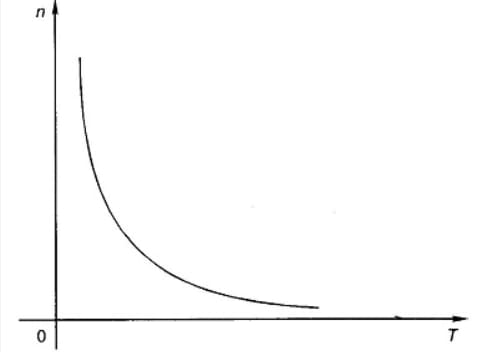
The speed-torque curve of a series DC motor is hyperbolic. At low torque (high speed), the curve is steep, and as the torque increases, the speed decreases rapidly.
-
Shunt DC Motor:
-
Speed-Torque Relationship: Characteristic: The speed of a shunt DC motor remains relatively constant with varying load torque. Behavior: The field current is nearly constant because it is determined by the supply voltage and the field resistance. Therefore, the field flux remains relatively constant. As the load torque increases, the armature current increases slightly, causing a small drop in speed.
In case of shunt DC Motor,
......(1)
..........(2)
So from these 2 equations, we can conclude that Speed and Torque both has a linear relationship.

The speed-torque curve of a shunt DC motor is relatively flat, indicating minimal change in speed with changes in torque.
-
-
Compound DC Motor:
-
Speed-Torque Relationship:
Characteristic: The speed-torque characteristics of a compound DC motor combine the features of both series and shunt motors. The relationship can be designed to provide a balance between high starting torque and relatively constant speed. Behavior: The motor has better starting torque than a shunt motor and better speed regulation than a series motor.
Compound motor characteristics basically depend on the fact whether the motor is cumulatively compound or differential compound. All the characteristics of the compound motor are the combination of the shunt and series characteristics.
-
A cumulative compound motor is capable of developing a large amount of torque at low speed just like a series motor. However, it is not having a disadvantage of the series motor even at the light or no load.
-
In a differential compound motor, as two fluxes oppose each other, the resultant flux decreases as load increases, thus the machine runs at a higher speed with an increase in load. This property is dangerous as on full load, the motor may try to run with dangerously high speed. So the differential compound motor is generally not used in practice.

The speed-torque curve of a compound DC motor lies between that of a series and a shunt motor. It shows moderate speed regulation with a good starting torque.
-
Numerical
Conversion Efficiency
The conversion efficiency of a DC motor refers to the ratio of the mechanical power output to the electrical power input, expressed as a percentage. It is a measure of how effectively the motor converts electrical energy into mechanical energy.
Factors Affecting Efficiency
-
Copper Losses:
- Armature Resistance: Losses due to the resistance of the armature windings.
- Field Winding Resistance: Losses due to the resistance of the field windings (in the case of separately excited or shunt-wound DC motors).
-
Iron Losses (Core Losses):
- Hysteresis Loss: Due to the repeated magnetization and demagnetization of the core material.
- Eddy Current Loss: Induced currents within the core material due to the alternating magnetic field, generating heat.
-
Mechanical Losses:
- Friction Losses: Due to friction in bearings and other moving parts.
- Windage Losses: Due to air resistance as the rotor spins.
-
Brush Losses:
- Losses due to the resistance at the contact points between the brushes and the commutator.
Load Conditions:
- Efficiency varies with load and typically reaches its maximum at or near the rated load.
Calculation of Efficiency
Efficiency (η): Efficiency is the ratio of the output power to the input power, expressed as a percentage. The efficiency (η) of the DC motor is the ratio of the useful output mechanical power to the input electrical power:
=
Where:
- is the output power (in watts, W).
- is the input power (in watts, W).
Applications
DC motors are widely used in various applications due to their simple design, ease of control, and wide range of speed and torque characteristics.
-
Industrial Applications:
DC motors are used in conveyor belts for materials handling in factories and warehouses due to their variable speed control. Employed in lifting and lowering heavy loads with precise speed and torque control. Used in steel mills and other industries where varying speed and high torque are required.
-
Transportation:
DC motors power electric cars, buses, and other vehicles, offering efficient speed control and high torque. Used in trains, trams, and trolleys for their reliable performance and ease of speed control. Provide the necessary power for lifting and transporting materials in warehouses.
-
Home Appliances:
Small DC motors are used in cooling fans, exhaust fans, and blowers. Drills, saws, and other handheld power tools use DC motors for their compact size and powerful performance. Used in devices such as vacuum cleaners, electric shavers, and mixers.
-
Office Equipment:
DC motors drive the paper feed mechanism and print heads. Used to move the scanning head across the document. Drive various mechanical components in photocopiers.
-
Robotics:
DC motors act as actuators in robotic arms, providing precise movement and control. Used in mobile robots for propulsion and steering.
-
Medical Devices:
Used in powered surgical instruments for cutting, drilling, and other operations. Provide motion control in devices like MRI machines and X-ray equipment. DC motors drive the movement of artificial limbs.
-
Aerospace:
Used in flight control systems for actuating control surfaces. Provide precise control for antenna positioning and other mechanisms.
-
Portable Electronics:
Used in cooling fans to manage heat. Drive the lens mechanism for focusing and zooming.
-
HVAC Systems:
Small DC motors drive fans and compressors in HVAC systems. Used in refrigerators and freezers to drive the compressor and fans.