DC Generator Operating Principle
An electromechanical energy conversion device known as a DC generator uses electromagnetic principles to convert mechanical power into DC electrical power. According to the electromagnetic induction theory, an EMF is induced in a conductor when the magnetic flux connecting them changes. This is how a DC generator works. In a DC generator, there are two windings: the field and the armature.
The EMF made in the armature Winding of a DC generator is rotating and is switched over completely to coordinate voltage by a commutator introduced on the generator's shaft. A DC generator's armature winding is on the rotor, while the field winding is on the stator.
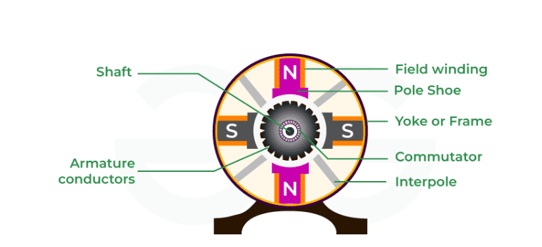
Components of DC Generator
Components of DC Generator are given below :
- Yoke
- Magnetic Field System
- Armature Core
- Armature Winding
- Commutator
- DC Generator Commutator Function
- Shaft
- Pole Shoe
- Poles
- Bearings
-
Yoke:
The outside frame of a DC generator is a hollow cylinder made of cast or rolled steel, known as a yoke. The yoke provides the following two objectives. It supports the field pole core and serves as a protective cover for the machine. It offers a channel for the magnetic flux produced by the field coil.
-
Magnetic Field System:
A DC generator's magnetic field system serves as its stationary component. It generates the primary magnetic flux in the generator. It is made up of a large number of pole cores fastened to the yoke with field winding coiled around the pole core. The field arrangement of a DC generator features prominent poles, such as poles that thrust inwards, and each pole core has a post shoe with a curved surface. The shaft shoe has two objectives. It provides support for the field coils. It lowers the reluctance of a magnetic circuit by expanding its cross-sectional area. To prevent eddy current loss, the pole cores are constructed of thin, insulated sheet steel laminations. The field coils are linked in series to create alternating north and south poles in the rotating direction as the current flows through them.
-
Armature Core:
The armature core of a DC generator is positioned on a shaft and pivots between the field poles. It features slots on its exterior surface where the armature conductors are installed. The armature core is made up of soft iron laminations that are isolated from one another and securely Attached together. In big machines, the laminations are keyed, but in tiny machines, they are keyed directly to the shaft. The laminated armature core helps to decrease eddy current losses.
-
Armature Winding:
The insulated conductors are inserted into the slots of the armature core. The wires are properly connected. The linked arrangement of conductors is known as armature winding. There are two types of armature windings used: wave winding and lap winding.
-
Commutator:
A commutator is a mechanical rectifier that converts the alternating magnetic field of the armature winding into a direct voltage that runs through the load terminals. The commutator is constructed up of wedge-shaped copper segments that are isolated from one another and the shaft by mica sheets. Each commutator segment is connected to one of the armature coil's ends.
-
DC Generator Commutator Function:
The basic purpose of the commutator is to convert DC to AC. It functions as a reversing switch, and its purpose in the generator is explained below. The electromagnetic field produced within the generator's armature coil alternates, leading to an alternating current flowing within the armature coil. This current may be reversed through the commutator at the precise moment that the armature coil crosses the magnetic unbiased axis. As a result, the load develops a DC or unidirectional current. The commutator ensures that the current flowing from the generator continues in the same direction indefinitely. By moving along the commutator, the brushes create high-quality electrical connections between the generator and the load.
-
Shaft:
The shaft is a key component of a DC machine because it produces torque, which causes rotation. It is constructed of mild steel and has the highest breaking strength. The shaft is a component of a DC generator that influences the generator's ability to transport mechanical energy. The shaft is keyed to the commutator, cooling fan, armature center, and other spinning components.
-
Pole Shoe: A pole shoe is a plate composed of iron or steel that spreads magnetic flux and prevents field coils from falling.
-
Poles: Poles help maintain the field windings in excellent shape. These windings are generally coiled on poles and linked in a certain order to the armature windings. As a result, the posts attach the welding procedure to the yoke using screws.
-
Bearings: Bearings are used in a system to ensure that the various parts of a DC machine move smoothly. The friction between the machine's spinning and stationary elements is reduced with the aid of course. As a result, the system's components require less frequent greasing and will last longer. Roller bearings and ball bearings are the two most popular types of bearings used in dc generators.
Workings of a DC Generator
Consider a single loop DC generator (as seen in the diagram), in which a single turn loop 'ABCD' rotates clockwise in a uniform magnetic field at constant speed. As the loop rotates, the magnetic flux between the coil sides 'AB' and 'CD' changes continually. This change in flux linkage causes an EMF to be induced in both coil sides, and the induced EMF on one coil side is added to the induced EMF on the other.
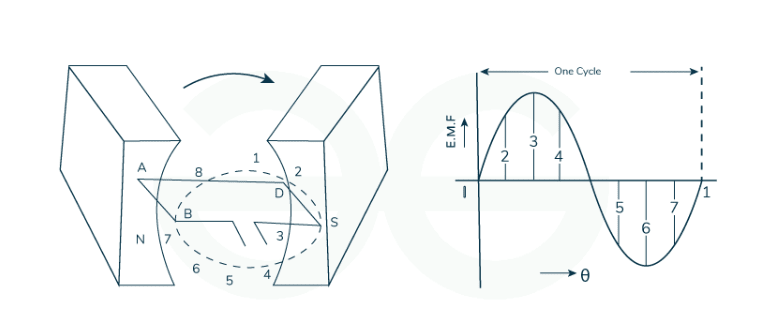
The EMF produced by a DC generator may be explained as follows:
- When the loop is at position 1, no EMF is produced since the coil sides move in parallel with the magnetic flux.
- When the loop is in position 2, the loop sides move in the direction of the attracting motion, generating a tiny EMF.
- When the loop is at place 3, the coil sides move at the right point to the attractive transition, resulting in the highest EMF.
- When the loop is in position 4, the coil sides cut the attractive transition at a point, resulting in a lower EMF in the coil sides.
- When the loop is at place 5, there is no motion coupling with the coil side, and the movement is aligned with the attractive transition. Consequently, no EMF is produced in the coil.
- At position 6, the coil sides move beneath an inverse extremity post, switching the extremity of the generated EMF. The most intense EMF will be produced toward this route at position-7, and zero at position-1. This cycle repeats for each coil turn.
It is evident that the produced EMF is a spinning one. It is because any coil side (for example, AB) has EMF in one direction when impacted by an N-pole and in the opposite direction when affected by an S-pole. As a result, when a load is attached to the generator's terminals, alternating current flows through it. Currently, using a commutator, the alternating emf created in the loop may be converted into direct voltage.
Numerical
Reversal Of Energy Transfer
DC Motor Acting as a DC Generator:
Process:
- Mechanical Input: Apply mechanical force to the motor's shaft, causing it to rotate.
- Induced EMF: As the armature windings rotate within the magnetic field, an EMF is induced in the windings.
- Electrical Output: The induced EMF causes a current to flow through the circuit, thus generating electrical power.
DC Generator Acting as a DC Motor:
Process:
- Electrical Input: Apply a DC voltage to the generator's armature windings.
- Lorentz Force: The current through the windings interacts with the magnetic field, producing a force on the conductors.
- Mechanical Output: The forces cause the armature to rotate, thus producing mechanical motion.
Key Factors in Reversibility
-
Design Similarities: Both DC motors and DC generators have similar construction with an armature, field windings, commutator, and brushes. This allows them to operate in either mode by changing the type of energy input.
-
External Prime Mover: For a motor to act as a generator, an external mechanical source must drive the rotation. Conversely, for a generator to act as a motor, an external electrical source must provide the driving current.
-
Circuit Configuration: The external circuit connected to the machine determines whether it operates as a motor or a generator. In motors, the circuit provides electrical power to create mechanical motion, while in generators, the circuit allows for the collection of electrical power generated by mechanical motion.
EMF and Speed Relationship
When the armature of a DC generator rotates in magnetic field, an emf is induced in the armature winding, this induced emf is known as generated emf. It is denoted by .
Derivation of EMF Equation of DC Generator
Let
- = Magnetic flux per pole in Wb
- = Total number of armature conductors
- = Number of poles in the machine
- = Number of parallel paths
Where,
- for Lap Winding
- for Wave Winding
Lap Winding: Number of parallel paths equals the number of poles . This configuration is typically used for machines requiring higher current and lower voltage.
Wave Winding: Number of parallel paths is fixed at 2, irrespective of the number of poles . This configuration is suitable for machines needing higher voltage and lower current.
= Speed of armature in RPM
= Generated EMF = EMF per parallel path
Therefore, the magnetic flux cut by one conductor in one revolution of the armature is,
Wb
The time taken to complete one revolution is given by,
Hence, according to the law of electromagnetic induction, the emf generated per conductor is,
Since the number of conductors in series per parallel path is,
Therefore,
Hence, the EMF equation of a DC generator is,
It is clear from eqn. (1) that for any DC generator , , and are constant so that . Therefore, for a given DC generator, the induced EMF in the armature is directly proportional to the flux per pole and the speed of rotation.
Case 1: For Lap winding, the number of parallel paths . Thus,
Case 2: For Wave winding, the number of parallel paths . Thus,
Case 3: For Custom winding, the number of parallel paths . Thus,
Numerical Example
A 6-pole, DC generator has 800 conductors on its armature. The flux per pole is 0.035 Wb. The speed of rotation of the armature is 1500 RPM. Calculate the generated EMF when the armature is, (a) Lap wound, (b) Wave wound.
Solution:
(a). For Lap wound armature −
= = = 700V
(b). For wave wound armature −
= = =2100V
Applications
DC generators have several applications across various industries and technologies.
-
Power Generation: DC generators are used in small-scale power generation setups where DC power is required. They can be used in remote areas or for specific applications where DC power is preferred over AC.
-
Battery Charging: DC generators are often used for charging batteries in automotive, marine, and other applications where a reliable source of DC power is needed to keep batteries charged.
-
Electroplating: DC generators are used in electroplating processes where a controlled DC current is required to deposit metals onto surfaces, such as in manufacturing and jewelry industries.
-
Welding: DC generators can provide the necessary DC current for welding processes, especially in remote locations or where portability is important.
-
Telecommunications: They are used in telecommunications applications where DC power is needed to operate equipment such as repeaters, amplifiers, and backup power systems.
-
Railway Traction: In some railway systems, DC generators (or DC motors acting as generators) are used for regenerative braking systems to recover energy during braking and feed it back into the power grid or batteries.
-
Research and Testing: DC generators are used in laboratories and research facilities for testing purposes where precise control over DC voltage and current is required.
-
Military Applications: They are used in military equipment and vehicles where ruggedness, reliability, and the ability to operate in harsh conditions are critical.
-
Hybrid Vehicles: In some hybrid vehicle designs, DC generators (often in the form of DC-DC converters) are used to manage power flow between different electrical systems within the vehicle.
-
Backup Power Systems: DC generators can be used in backup power systems where continuous DC power supply is essential, such as in critical infrastructure and data centers.