Logic Gates
A logic gate is an electronic circuit created using electronic components like diodes, transistors, resistors, and more. As the name implies, a logic gate is designed to perform logical operations in digital systems like computers, communication systems, etc.
Therefore, we can say that the building blocks of a digital circuit are logic gates, which execute numerous logical operations required by any digital circuit. A logic gate can take two or more inputs but produces only one output. The output of a logic gate depends on the combination of inputs and the logical operation that the logic gate performs.
Logic gates use Boolean algebra to execute logical processes and are found in nearly every digital gadget we use regularly. They are used in the architecture of our telephones, laptops, tablets, and memory devices.
Types of Logic Gates
A logic gate is a digital gate that allows data manipulation. Logic gates use logic to determine whether or not to pass a signal. Moreover, they govern the flow of information based on a set of rules.
The logic gates can be classified into the following major types:
-
Basic Logic Gates: There are three basic logic gates:
-
AND Gate:
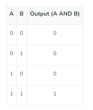
In digital electronics, the AND gate is one of the basic logic gates that performs the logical multiplication of the inputs applied to it. It generates a high or logic '1' output only when all the inputs are high or logic '1.' Otherwise, the output of the AND gate is low or logic '0.'
Properties of AND Gate:
The following are two main properties of the AND gate:
- An AND gate can accept two or more input values at a time.
- When all the inputs are logic '1,' the output of this gate is logic '1.'
The operation of an AND gate is described by a mathematical expression, called the Boolean expression of the AND gate. For a two-input AND gate, the Boolean expression is given by:
where A and B are inputs to the AND gate, and Z denotes the output.
Truth Table of AND Gate:
The truth table of a two-input AND gate is shown below:

Symbol of AND Gate:
The logic symbol of a two-input AND gate is shown in the following figure.

-
OR Gate:
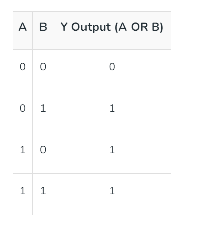
In digital electronics, the OR gate is a basic logic gate that produces a low or logic '0' output only when all its inputs are low or logic '0.' For all other input combinations, the output of the OR gate is high or logic '1.' An OR gate can have two or more inputs but produces only one output. The primary function of the OR gate is to perform the logical sum operation.
Properties of OR Gate:
An OR gate has the following two properties:
- It can have two or more input lines at a time.
- When all the inputs to the OR gate are low or logic '0,' the output is low or logic '0.'
The operation of an OR gate can be mathematically described using a Boolean expression. For a two-input OR gate, the expression is:
Truth Table of OR Gate:
The truth table of an OR gate shows the relationship between inputs and output. The following is the truth table for the two-input OR gate:

Symbol of OR Gate:
The logic symbol of a two-input OR gate is shown in the following figure.

-
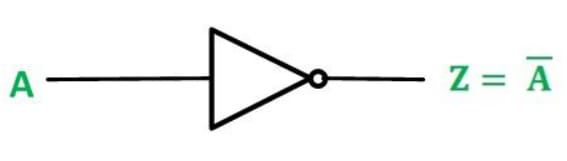
NOT Gate:
In digital electronics, the NOT gate is another basic logic gate used to perform the complement of an input signal. It takes only one input and produces one output. The output of the NOT gate is the complement of the input. If a low or logic '0' is applied to the NOT gate, it gives a high or logic '1' output, and vice-versa. The NOT gate is also known as an inverter, as it performs the inversion operation.
Properties of NOT Gate:
- The output of a NOT gate is the complement or inverse of the input.
- A NOT gate takes only one input.
The logical operation of the NOT gate is described by its Boolean expression:
The bar over input variable A represents the inversion operation.
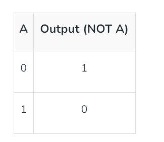
Truth Table of NOT Gate:
The truth table describes the relationship between input and output. The following is the truth table for the NOT gate:

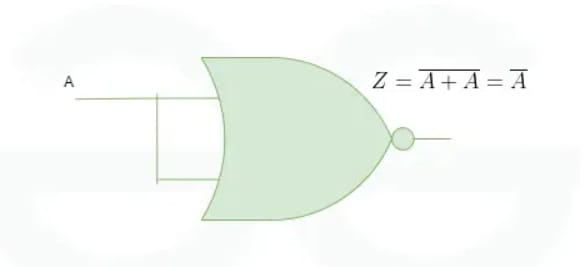
Symbol of NOT Gate:
The logic circuit symbol of a NOT gate is shown in the following figure. Here, A is the input line and Z is the output line.
-
-
Universal Logic Gates: In digital electronics, the following two logic gates are considered universal logic gates:
-
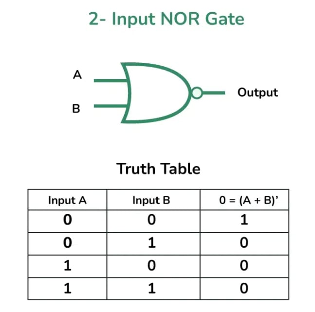
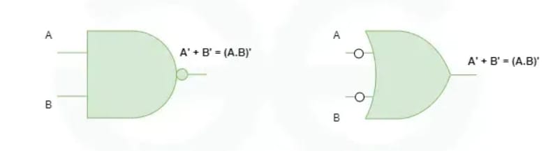
NOR Gate:
The NOR gate is a type of universal logic gate that can take two or more inputs but has only one output. It is essentially a combination of two basic logic gates, i.e., an OR gate followed by a NOT gate. Thus, it can be expressed as:
NOR Gate = OR Gate + NOT Gate
Properties of NOR Gate:
The following are two important properties of the NOR gate:
- A NOR gate can have two or more inputs and produces one output.
- A NOR gate gives a high or logic '1' output only when all its inputs are low or logic '0.'
Similar to basic logic gates, the operation of a NOR gate can be described using a Boolean expression.
The Boolean expression of a two-input NOR gate is:
In the above Boolean expression, the variables A and B are the input variables, while C is the output variable.
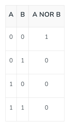
Truth Table of NOR Gate:
The following is the truth table of a two-input NOR gate showing the relationship between its inputs and output:

Symbol of NOR Gate:
The logic circuit symbol of a NOR gate is shown in the following figure.

-
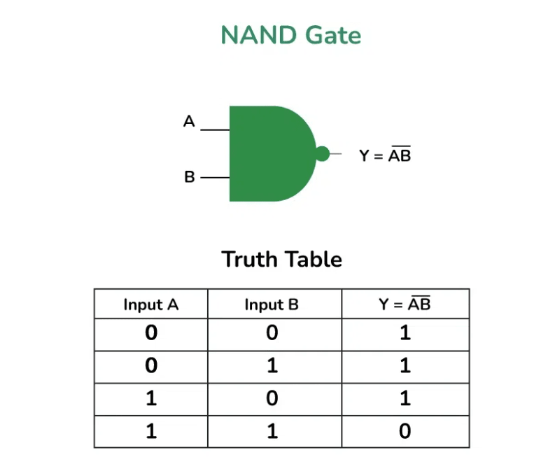
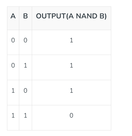
NAND Gate:
In digital electronics, the NAND gate is another type of universal logic gate used to perform logical operations. The NAND gate performs the inverted operation of the AND gate. Similar to the NOR gate, the NAND gate can also have two or more input lines but only one output line.
The NAND gate can be represented as a combination of two basic logic gates, namely, the AND gate and the NOT gate. Hence, it can be expressed as:
NAND Gate = AND Gate + NOT Gate
Properties of the NAND Gate:
The following are the two key properties of the NAND gate:
- The NAND gate can take two or more inputs at a time and produce one output based on the combination of inputs applied.
- The NAND gate produces a low or logic 0 output only when all its inputs are high or logic 1.
We can describe the expression of the NAND gate through a mathematical equation called its Boolean expression. Here is the Boolean expression of a two-input NAND gate:
In this expression, and are the input variables, and is the output variable. We can extend this relationship to any number of input variables, such as three, four, or more.
Truth Table of the NAND Gate:
The truth table is a table of inputs and outputs that describes the operation of the NAND gate and shows the logical relationship between them:

Symbol of the NAND Gate:
The logic symbol of a NAND gate is represented as an AND gate with a bubble on its output end, as depicted in the following figure. This is the symbol of a two-input NAND gate.

-
-
Derived Logic Gates:
The following two are the derived logic gates used in digital systems:
-
XOR Gate:
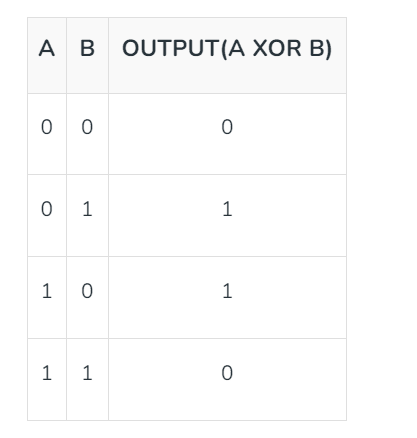
In digital electronics, there is a specially designed logic gate named the XOR gate, which is used in digital circuits to perform the modulo sum. It is also referred to as the Exclusive OR gate or Ex-OR gate. The XOR gate can take two inputs at a time and give one output. The output of the XOR gate is high or logic 1 only when its two inputs are dissimilar.
Properties of the XOR Gate:
The following are the main properties of the XOR gate:
- It can accept only two inputs at a time. There is nothing like a three-input or more-input XOR gate.
- The output of the XOR gate is logic 1 or high when its inputs are dissimilar.
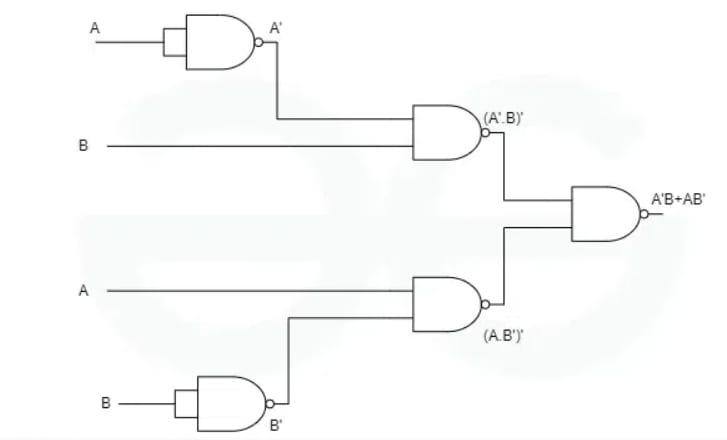
The operation of the XOR gate can be described through a mathematical equation called its Boolean expression. The following is the Boolean expression for the output of the XOR gate:
Here, is the output variable, and and are the input variables.
This expression can also be written as follows:
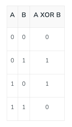
Truth Table of the XOR Gate:
The truth table describes the relationship between inputs and outputs and the operation of the XOR gate for different input combinations. The truth table of the XOR gate is given below:

Symbol of the XOR Gate:
The logic symbol of an XOR gate is shown in the following figure.

-
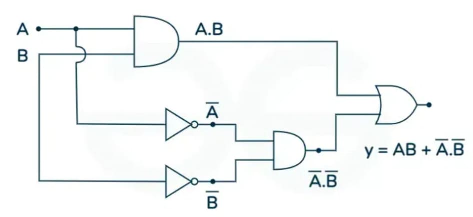
XNOR Gate:
The XNOR gate is another type of special-purpose logic gate used to implement exclusive operations in digital circuits. It is used to implement the Exclusive NOR operation in digital circuits. It is also called the Ex-NOR or Exclusive NOR gate. It is a combination of two logic gates, namely, the XOR gate and the NOT gate. Thus, it can be expressed as:
XNOR Gate = XOR Gate + NOT Gate
The output of an XNOR gate is high or logic 1 when both its inputs are similar. Otherwise, the output is low or logic 0. Hence, the XNOR gate is used as a similarity detector circuit.
Properties of the XNOR Gate:
The following are two key properties of the XNOR gate:
- The XNOR gate takes only two inputs and produces one output.
- The output of the XNOR gate is high or logic 1 only when it has similar inputs.
The operation of the XNOR gate can be described through a mathematical equation called the Boolean expression of the XNOR gate. Here is the Boolean expression of the XNOR gate:
We can also write this expression as follows:
Here, and are inputs, and is the output.
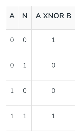
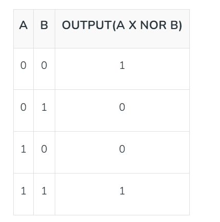
Truth Table of the XNOR Gate:
The truth table of the XNOR gate is given below. This truth table describes the relationship between the inputs and output of the XNOR gate.

Symbol of the XNOR Gate:
The logic symbol of the XNOR gate is shown in the following figure. Here, and are inputs, and is the output.

-
Applications of Logic Gates
Logic gates are the fundamental building blocks of all digital circuits and devices such as computers. Here are some key digital devices that utilize logic gates in their circuit design:
- Computers
- Microprocessors
- Microcontrollers
- Digital and smartwatches
- Smartphones, etc.
Concept of Universal Gates
Universal gates are logic gates that are versatile enough to perform any Boolean function. The most common universal gates are NAND and NOR gates.
To elaborate, the inputs of universal gates can be interconnected and inverted in various ways to replicate the functionality of the basic AND, OR, NOT, XOR, and XNOR gates.
These gates are highly versatile and serve as core components in the implementation of digital circuits and processors. By using just a single type of gate or a combination of both NAND and NOR gates, intricate logic systems can be constructed.
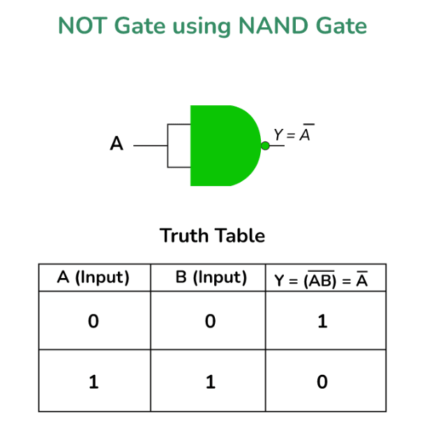
NAND Gate
A NAND gate is essentially an AND gate followed by a NOT gate. It outputs a 0 only when all its inputs are 1; otherwise, it outputs 1.
Symbol and Truth Table:
NOR Gate
A NOR gate is a combination of an OR gate followed by a NOT gate. It outputs a 1 only when all its inputs are 0; otherwise, it outputs 0.
Symbol and Truth Table:
Implementing Basic Gates Using a NAND Gate
1. NOT Gate (Inverter):
Connect both inputs of a NAND gate to the same input signal.
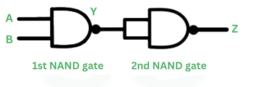
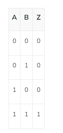
2. AND Gate:
Connect the outputs of two NAND gates to the inputs of a third NAND gate.
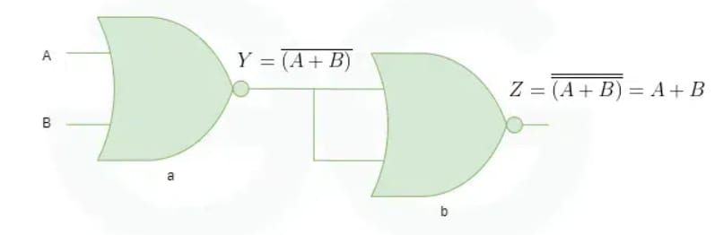
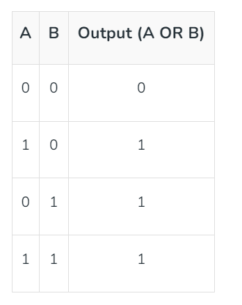
3. OR Gate:
Connect each input to a NAND gate, then connect the outputs of these gates to the inputs of another NAND gate.
4. NOR Gate:
Connect the outputs of two NAND gates to the inputs of a third NAND gate. Then, feed the output of this gate into another NAND gate configured as a NOT gate.
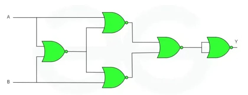
5. XOR Gate:
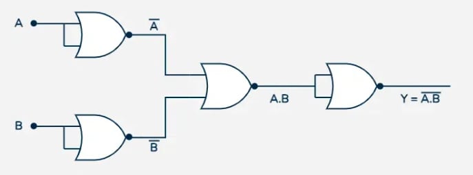
Use a combination of four NAND gates.
6. XNOR Gate:
Connect the output of an XOR gate to a NAND gate configured as a NOT gate.
Implementing Basic Gates Using a NOR Gate
1. NOT Gate (Inverter):
Connect both inputs of a NOR gate to the same input signal.
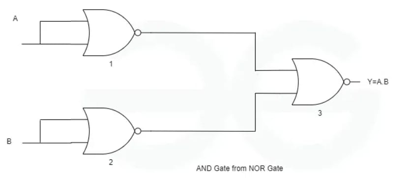
2. AND Gate:
Use three NOR gates. First, connect each input to a NOR gate and then connect their outputs to the inputs of another NOR gate.
3. OR Gate:
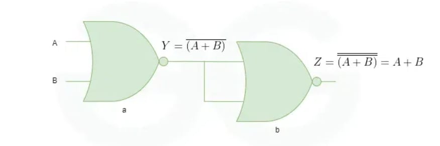
Use a combination of NOR gates, with the final gate configured as a NOT gate.
4. NAND Gate:
Use a combination of three NOR gates.
5. XOR Gate:
Utilize a combination of five NOR gates.
6. XNOR Gate:
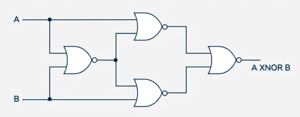
Connect the output of an XOR gate (realized using NOR gates) to another NOR gate configured as a NOT gate.
Applications of Universal Logic Gates
- NAND and NOR gates serve as the basic building blocks for microprocessors and other integrated circuits (ICs) with complex functionalities.
- Universal gates enable the implementation of any Boolean function using a single gate type, making them very efficient in circuit design.
- In Field-Programmable Gate Arrays (FPGAs), logic functions are often implemented using lookup tables made up of NAND or NOR gates, defined by the user.
- These gates allow engineers to design circuits with the fewest components since the entire design can be created using just NAND or NOR gates.
- Universal gates can be interconnected to form standard digital subcircuits, such as adders, decoders, encoders, multiplexers, and demultiplexers.
- Their controllability and scalability make them suitable for designing circuits involving addition, flip-flops, and memory.