Electronic Instruments
Electronic Instruments are devices used to measure, monitor, and analyze electrical and electronic parameters in circuits and systems. These instruments play a critical role in testing, development, and maintenance across various fields like electronics, telecommunications, and industrial applications.
Types of Electronic Instruments
-
Multimeter: A Multimeter is a versatile instrument that can measure multiple electrical parameters such as voltage (AC/DC), current, and resistance. Advanced versions may also measure frequency, capacitance, and temperature.
-
Oscilloscope: An Oscilloscope (or CRO, Cathode Ray Oscilloscope) is used to display and analyze the waveform of electronic signals. It helps in visualizing how voltage varies with time.
-
Signal Generator: A Signal Generator produces standardized waveforms (sine, square, triangle, etc.) for testing and development purposes. It’s essential in verifying the behavior of circuits and systems under various conditions.
Cathode Ray Oscilloscope (CRO)
A cathode ray oscilloscope (CRO) is an electronic test instrument used to visualize waveforms of electrical signals. It was originally known as an oscilloscope. The oscilloscope monitors the changes in electrical signals over time, with voltage and time plotted to form a waveform on a screen. By analyzing the waveform, we can determine properties such as amplitude, frequency, rise time, time interval, distortion, etc.
The CRO consists of four main sections: the display, vertical controls, horizontal controls, and triggers. Most oscilloscopes use probes to input signals into the instrument. Waveforms are analyzed by plotting amplitude on the y-axis and time on the x-axis. CROs are commonly used in radio and TV receivers, as well as for research and design in laboratories. In modern electronics, the CRO plays an important role in analyzing electronic circuits.
Block Diagram of Cathode Ray Oscilloscope (CRO)
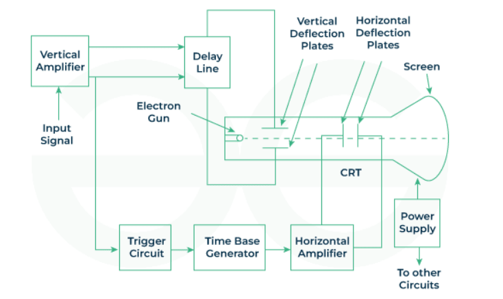
The cathode ray tube (CRT) is the heart of an oscilloscope. In a CRO, the CRT generates a stream of electrons, accelerated to high speed, and focuses them onto a fluorescent screen.
The screen shows a bright spot where the electron beam strikes. This beam behaves like a pencil of light, responding to electrical signals by moving across the screen.
Various electrical signals and voltages are needed to operate the oscilloscope. The power supply provides both high and low voltages: low voltage powers the electron gun heater, generating the electron beam, and high voltage accelerates the beam. Other control units of the oscilloscope also use these voltages.
The horizontal and vertical plates are located between the electron gun and the screen, allowing the beam to be deflected according to the input signal. Before deflecting the electron beam horizontally (along the X-axis) at a constant time-dependent rate, a time base generator is provided by an oscillator.
The input signal is passed through vertical deflection plates via the vertical amplifier, which amplifies the signal to control the electron beam's deflection. When the electron beam is deflected along both the X and Y axes, a trigger circuit synchronizes the two deflections, ensuring that the input signal and horizontal deflection start at the same point.
Construction of Cathode Ray Oscilloscope
The construction of a cathode ray oscilloscope consists of the following components:
- Cathode Ray Tube (CRT)
- Electron Gun
- Deflecting Plates
- Fluorescent Screen
- Glass Envelope
1. Cathode Ray Tube (CRT):
The CRO is a vacuum tube, and its main function is to convert electrical signals into visual ones. The tube contains an electron gun and electrostatic deflection plates. The electron gun produces a focused, high-speed electron beam. The vertical deflection plates move the beam up and down, while the horizontal deflection plates move the beam from left to right. These movements are independent, allowing the beam to be positioned anywhere on the screen.
2. Electron Gun:
The electron gun's main function is to emit and form electrons into a beam. It typically consists of a heater, cathode, control grid, and accelerating anodes. The cathode emits electrons, and the control grid regulates the number of electrons. The electrons are then accelerated and focused by the anodes, passing through the deflection plates (horizontal and vertical) before striking the fluorescent screen.
3. Deflecting Plates:
After leaving the electron gun, the electron beam passes through two sets of deflecting plates. The vertical deflecting plates (Y plates) control vertical movement, while the horizontal deflecting plates (X plates) control horizontal movement.
4. Fluorescent Screen:
The front face of the CRT is called the faceplate, and it is coated with a phosphor material. When the electron beam strikes the phosphor coating, light is emitted, creating a visible spot on the screen. This process is called fluorescence.
5. Glass Envelope:
The glass envelope is a highly evacuated, cone-shaped structure. The inner surface between the neck and the display is coated with a material called aquadag, which is conductive and serves as a high-voltage electrode. This helps the electron beam to focus on the center of the screen.
Working of Cathode Ray Oscilloscope
The CRO works on the principle of electron beam deflection due to electrostatic forces. When the electron beam hits the phosphor-coated screen, it creates a bright spot. Electrostatic deflection forces from two perpendicular directions move the spot across the screen, forming a waveform that represents the input signal.
The vertical deflection system amplifies weak signals so that the amplified signal can deflect the electron beam. The input signals are sent to the vertical deflection plates through the attenuator and amplifier stages.
The horizontal deflection system works similarly but includes a sweep voltage to create a time base. A sawtooth wave generator provides the input to the horizontal amplifier, creating a continuous sweep across the screen.
-
Recurrent Sweep: This mode starts a new sweep automatically at the end of the previous one.
-
Triggered Sweep: In this mode, the sweep starts only when a trigger event occurs, useful for viewing signals that are not continuous.
-
Driven Sweep: Used when the sweep is free-running but triggered by the signal under test.
-
Non-Sawtooth Sweep: Used to compare the input signal voltages and analyze frequency differences.
-
Synchronization: Synchronization ensures that the sweep and the signal are in sync, producing a stable display. It can be done using internal, external, or line triggers.
- Internal: Uses the signal being measured for synchronization.
- External: Uses an external trigger source.
- Line: Uses the power supply for synchronization.
-
Intensity Modulation: This feature adjusts the brightness of the display by applying a signal between the cathode and ground.
-
Position Control: Allows the user to adjust the position of the signal on the screen using an internal voltage source.
-
Intensity Control: Adjusts the display's brightness by varying the grid potential relative to the cathode.
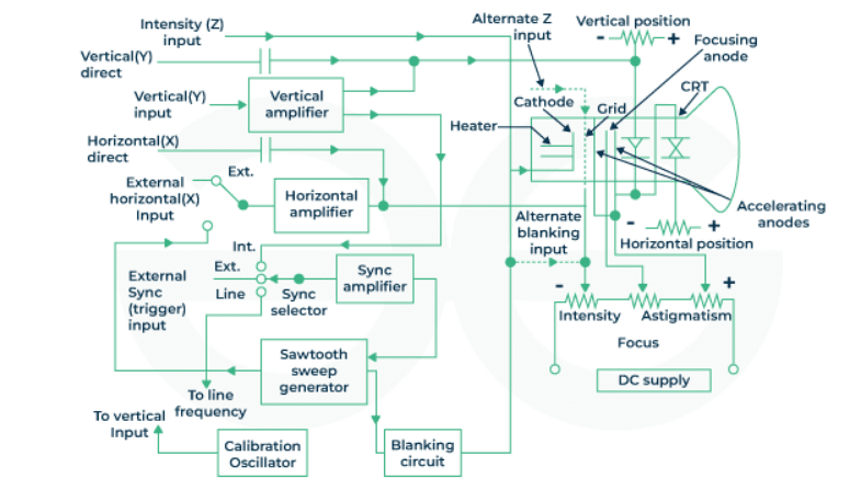
Controls of Cathode Ray Oscilloscope
The fundamental controls of a CRO primarily include position, brightness, focus, astigmatism, blanking, and calibration.
-
Position: In the oscilloscope, the position control knob is mainly used to adjust the position of the bright spot from left to right. By adjusting the knob, one can control the spot's movement horizontally across the screen.
-
Calibration Circuit: The calibration circuit of an oscilloscope requires an oscillator. The oscillator used should generate a square waveform with a preset voltage.
-
Focus: By adjusting the voltage applied to the CRO’s focus anode, the focus of the electron beam can be controlled. The focus anode and other surrounding anodes form an electrostatic lens. Adjusting the voltage across the focus anode changes the focal length of the lens, allowing for sharper images.
-
Blanking Circuit: The time base generator in the oscilloscope produces a blanking voltage, which suppresses the electron beam when it is not required for display, ensuring that only relevant portions of the signal are shown.
-
Brightness: The brightness of the electron beam is determined by the intensity of the electron flow. The control grids regulate this intensity, allowing adjustment of the brightness by changing the voltage applied to the grid.
Applications of Cathode Ray Oscilloscope
The applications of a CRO include:
-
Waveform Analysis: The primary use of CROs is to visualize and analyze waveforms. Engineers and researchers can observe the duration, shape, magnitude, and structure of electrical signals over time. This capability is essential for analyzing signal behavior and detecting issues in electronic circuits, such as waveform distortion, noise, and anomalies.
-
Time Domain Analysis: CROs are used to analyze the time-domain behavior of signals, helping experts understand how signals change and interact over time. This is crucial for identifying signal irregularities and transient events, aiding in troubleshooting electronic circuits.
-
Pulse and Transition Time Measurement: CROs are used to measure pulse widths and transition times in digital circuits. This is important for assessing digital system performance and timing characteristics, ensuring signal integrity and timing accuracy.
-
Voltage Measurement: CROs provide precise voltage measurements in signals. This function is essential for characterizing and validating electronic systems by measuring peak-to-peak voltages, amplitudes, and DC offsets in various electrical signals.
-
Oscillator Testing: CROs play a critical role in testing and analyzing the performance of oscillators, which generate periodic waveforms. This includes evaluating the frequency stability and waveform characteristics of oscillators used in electronic systems.
-
Filter Testing: Engineers use CROs to evaluate the performance of electronic filters by observing their effect on waveforms. This involves assessing a filter's frequency response and attenuation properties, ensuring proper functionality in signal processing applications.
-
Frequency Measurement: CROs allow for accurate frequency measurement of repetitive waveforms. By using the time base settings on the oscilloscope, users can determine the period of the signal and calculate its frequency.
-
Transient Analysis: CROs are vital for capturing and analyzing transient phenomena in electronic circuits. Transients are sudden and brief changes in voltage, which can affect the stability and reliability of a system. CROs help study and analyze these disturbances, such as voltage spikes or surges.
-
Measurement of Phase: CROs facilitate the measurement and observation of phase differences between various signals, which is important for synchronizing and aligning signals in communication systems and control circuits.
-
Audio and Video Applications: CROs are used in the audio and video industries to analyze signals related to sound and image processing. This includes checking video signal quality and analyzing the frequency response of audio signals to ensure fidelity and performance in broadcasting and entertainment.
Advantages of Cathode Ray Oscilloscope
-
Real-time Visualization: CROs provide real-time visualization of electrical signals, allowing users to observe waveforms and signal characteristics as they happen.
-
Dynamic Signal Observation: CROs enable the observation of dynamic signal changes, making them valuable for studying rapidly changing signals, such as pulses or modulated waveforms.
-
High Accuracy: CROs offer precise measurements of waveform parameters such as amplitude, frequency, and phase, making them reliable instruments for accurate signal analysis.
-
Versatility: CROs are versatile tools for waveform analysis, applicable across various fields including electronics, telecommunications, medicine, and physics.
-
Educational Tool: CROs are useful teaching tools in electronics education, giving students a hands-on way to visualize and understand electrical signals.
-
Time Domain Analysis: CROs are essential for time-domain analysis, allowing users to study how signals behave over time and analyze transient phenomena in electronic circuits.
-
User-Friendly: Modern digital CROs have intuitive user interfaces with features like automatic measurements and on-screen menus, enhancing the user experience and making them accessible to a wide range of users.
-
Quick Troubleshooting: CROs enable rapid identification and troubleshooting of electronic circuit issues by providing a visual representation of signals, allowing engineers to quickly pinpoint irregularities.
Disadvantages of Cathode Ray Oscilloscope
-
Susceptibility to Electromagnetic Interference: CROs can be sensitive to electromagnetic interference, which may affect signal accuracy. Proper shielding and careful placement are necessary to minimize interference.
-
Limited Bandwidth: Some CRO models may have limited bandwidth, restricting their ability to accurately represent high-frequency signals. High-frequency applications may require specialized oscilloscopes.
-
Cost: High-quality CROs can be expensive, especially those with advanced features. This cost may be a concern for budget-constrained users or small laboratories.
-
Limited Storage Capacity: Analog CROs may have limited storage capacity for waveform data. While digital CROs offer better data storage, the storage capacity can still be a limitation in certain applications.
-
Mass and Weight: Traditional analog CROs can be bulky and heavy, making them difficult to transport. Although modern digital oscilloscopes are more compact, size and weight can still be a concern in some applications.
-
Risk of Electric Shock: Cathode ray tubes operate at high voltages, posing a risk of electric shock if proper safety precautions are not taken during maintenance or repairs.
-
Complexity for Novice Users: Some advanced features of CROs may be overwhelming for novice users. Training and familiarity with the instrument are essential for optimal use, especially in complex applications.
Signal Generator
A Signal Generator is an electronic device used to create various types of electrical signals in different waveforms, amplitudes, and frequencies. It serves as a versatile tool for testing, measurement, equipment diagnosis, and maintenance in electronic systems. Signal generators include components like oscillators, modulators, and frequency control circuits to generate the desired signals.
Features of Signal Generators
-
Frequency Range: This defines the number of cycles per second (Hertz) in the waveform. A broader frequency range enhances accuracy in testing diverse devices and systems.
-
Amplitude Range: Amplitude represents the peak height of a signal's frequency. A wider amplitude range ensures precision and adaptability in signal generation to meet application-specific requirements.
-
Output Power: Indicates the power level supplied by the generator. Correct power levels are essential for accurate signal generation.
-
Modulation Capabilities: This feature allows modification of one or more properties of a carrier signal, such as amplitude or phase, to encode data.
-
Sweep and Burst Functions: These functions enable signal generation across a specified frequency range or duration, crucial for testing periodic signals.
-
Waveform Format: The signal's shape, whether sine, square, triangle, or another form, determines the waveform's characteristics.
-
Triggering Options: Allows signal synchronization with external events or signals.
-
Waveform Memory: Permits storing and recalling waveforms for future use.
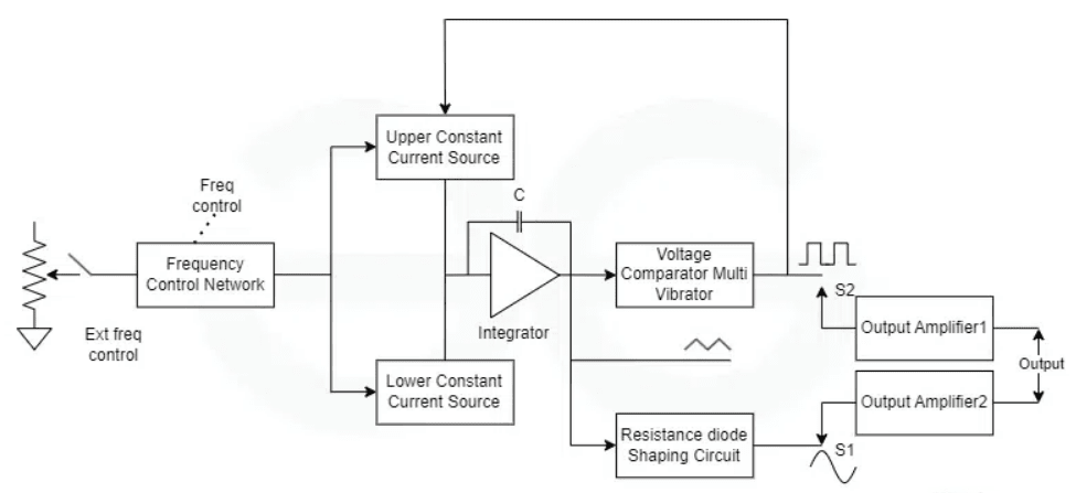
Signal Generator Block Diagram
Below is the block diagram of a signal generator, illustrating its internal components such as the oscillator, frequency control, waveform shaping, and modulation circuits.
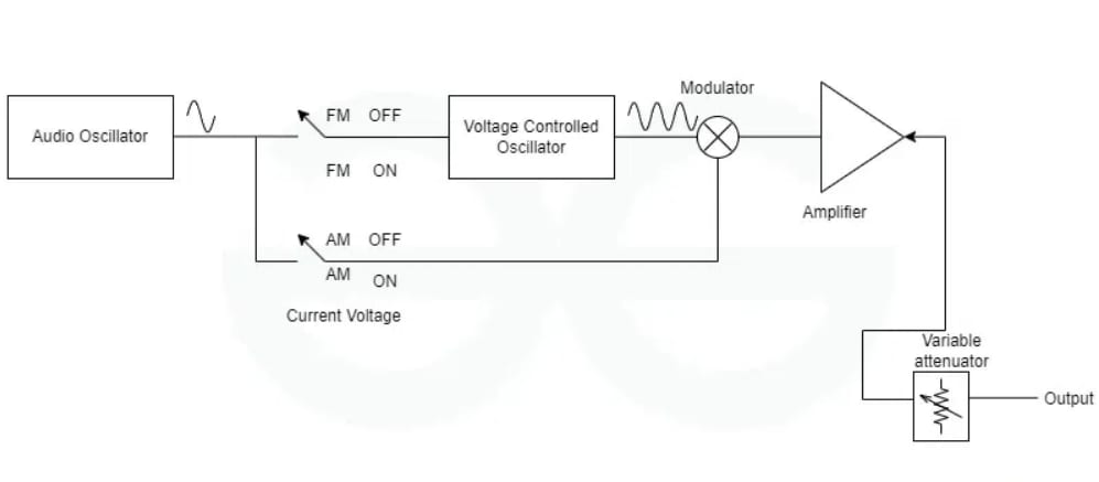
Signal Generator Circuit Diagram
A simplified circuit diagram helps visualize how key components like the oscillator, modulator, and frequency control are interconnected.
Types of Signal Generators
-
RF Signal Generator:
- Produces radio frequency signals used in wireless communication.
- Applications: Testing RF devices, communication systems, and antennas.
- Features: Precise control over frequency and modulation for RF applications.
-
Vector Signal Generator:
- Generates complex signals with both amplitude and phase modulation.
- Applications: Testing communication systems using advanced modulation schemes like QAM or PSK.
- Features: Independent control of in-phase (I) and quadrature (Q) components.
-
Arbitrary Waveform Generator:
- Creates custom waveforms, providing flexibility in testing and simulating real-world signals.
- Applications: Research, development, and prototyping requiring detailed waveform control.
- Features: High sampling rates and memory for complex waveform storage.
-
Audio Signal Generators:
- Produces audible signals (20 Hz to 20 kHz) for audio system testing.
- Applications: Checking frequency response and distortion in audio devices.
-
Video Signal Generators:
- Generates high-quality video outputs, essential for TV signal synchronization and video display testing.
- Applications: Ensuring proper video synchronization signals.
-
Function Generator:
- Produces standard waveforms (sine, square, triangular) for various applications.
- Applications: Circuit testing, educational use, and waveform generation for audio testing.
- Features: Adjustable frequency, amplitude, and waveform type.
-
Pulse Generator:
- Generates pulses with varying widths and frequencies for applications like digital circuit testing and radar systems.
- Applications: Pulse-width modulation and radar system testing.
- Features: Precise control over pulse width, frequency, and amplitude.
Advantages of Signal Generators
- Multipurpose: Adaptable for testing and repairing a wide range of electronic equipment.
- Precision: High-quality signal generators provide accurate control over waveform characteristics.
- Easy to Use: Suitable for beginners and professionals alike, with user-friendly modern features.
- Simulation of Real-World Conditions: Allows the testing of devices under various real-world signal conditions in a controlled environment.
Disadvantages of Signal Generators
- Cost: High-quality generators are often expensive, particularly those with specialized features.
- Complexity: Advanced features require a deep understanding of electronics, which can be challenging for beginners.
- Limited Physical Realism: Signal generators can't always replicate the full physical environment for certain applications.
- Size and Portability: Some generators are bulky and not easily portable, limiting their use in field testing.
Applications of Signal Generators
- Testing Communication Systems: Verifies the operation of communication devices like radios, mobile networks, and radars.
- Audio Equipment Testing: Ensures that audio systems, such as speakers and amplifiers, perform as expected.
- Radar System Testing: Calibrates radar systems by detecting and processing signals.
- Electronic Circuit Design: Assists engineers in testing and improving circuit performance.
- Education and Training: Used in academic settings to help students understand signal behavior.
- Power Electronics Testing: Plays a crucial role in testing and optimizing power electronics, inverters, and converters.
Measurement of Voltage, Phase, and Frequency using CRO
A Cathode Ray Oscilloscope (CRO) is a widely used instrument for measuring various electrical parameters such as voltage, phase, and frequency.
-
Measurement of Voltage
-
Peak Voltage:
To measure the peak voltage of a signal, connect the signal to the vertical input of the CRO and adjust the vertical gain so the waveform is visible. The peak voltage is determined by counting the number of vertical divisions the waveform covers from the baseline to the peak and multiplying it by the volts per division setting.
-
Peak-to-Peak Voltage:
For the peak-to-peak voltage, measure the vertical distance from the positive peak to the negative peak of the waveform. The peak-to-peak voltage is calculated as:
-
RMS Voltage:
For a sinusoidal waveform, the Root Mean Square (RMS) voltage is derived from the peak voltage using the formula:
-
-
Measurement of Phase Difference
-
Phase Difference Between Two Signals:
To measure the phase difference between two signals, connect one signal to the vertical input and the other to the horizontal input (or use a dual-trace CRO). Adjust the time base so that both waveforms are displayed. Measure the horizontal distance between corresponding points (e.g., peaks) of the two waveforms. The phase difference is then calculated as:
Where:
- is the time difference between the two signals.
- is the time period of the waveform.
-
-
Measurement of Frequency
-
Frequency of a Signal:
To measure frequency, display the signal on the screen and measure the time period of one complete cycle (e.g., from peak to peak). The frequency is the reciprocal of the time period:
Where:
-