Fundamental Ideas About Optical Fiber
Topic asked in Applied Physics 2023 (CBCS/NEP) question paper Section B - 4(a).
In communication systems, there has been frequent use of either radio waves or microwaves as carrier waves for sending information. However, the advent of the laser in 1960 revolutionized telecommunications and networking, with an immediate appreciation of the potential benefits of using light to send information from one place to another, as the laser is a coherent source of light waves.
It is worth mentioning that at higher optical frequencies Hz, one hundred thousand times more information can be carried compared to microwaves. However, the energy of light waves dissipates in the open atmosphere, so they cannot travel long distances. Hence, a guiding channel is required to guide them, just like a metal wire is required to guide electrical currents. This purpose is served with the use of optical fiber.
Optical fiber is a very thin glass or plastic conduit designed to guide light waves along the length of the fiber. As long as the refractive index of this fiber is greater than that of its surrounding medium, the light will undergo a large number of total internal reflections, and hence much of the light launched into one end will emerge from the other end with minimal losses.
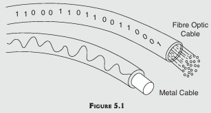
Fiber optics is a technology that uses glass, plastic, threads, or fibers to transmit data. A fiber optic cable consists of a bundle of glass threads (Fig. 5.1) protected by the cable's outer covering, called a jacket, which is made of treated paper, PVC, or metal. Optical fiber has several advantages over the copper wire used for electrical connections. For example, optical fiber, being made of glass or sometimes plastic, is protected from electromagnetic interference, such as that caused by thunderstorms.
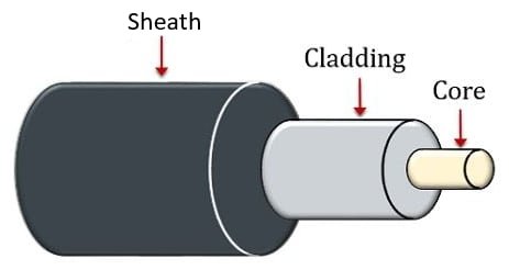
A single optical fiber consists of three parts: the core, cladding, and sheath (protective layer), as shown in above figure. The core is the thin glass center of the fiber where the light travels. The cladding is the outer optical material surrounding the core that reflects the light back into the core because the cladding has a lower refractive index. The sheath is a plastic coating that protects the fiber from damage and moisture.
To understand the advantages of fiber optics, it is necessary to know about bandwidth in general. Bandwidth is the difference between the upper and lower cutoff frequencies of a filter, a communication channel, or a signal spectrum. It is typically measured in Hertz. In the case of a low-pass filter or baseband signal, the bandwidth is equal to its upper cutoff frequency. In radio communications, bandwidth is the range of frequencies occupied by a modulated carrier wave. For example, an FM radio receiver's tuner spans a limited range of frequencies. In optics, bandwidth refers to the width of an individual spectral line or the entire spectral range.
Fiber optics has many advantages compared with traditional metal communications lines, which are listed as follows:
- Fiber optic cables can carry more data because their bandwidth is greater than that of metal cables.
- Fiber optic cables are less susceptible to interference compared to metal cables.
- Fiber optic cables are much thinner and lighter than metal wires.
- Through fiber optic cables, data can be transmitted digitally rather than analogically.
- Attenuation through fiber optic cables is very low when transmitting data over long distances, so there is no need for repeaters.
Propagation Mechanism
Optical fibers use light to carry digital signals, and the basis of this technology is the concept of total internal reflection. The digital signal carried by the light is reflected inside the optical cable, thereby transferring the information. The main concepts of physics involved in optical fibers are refraction, refractive indices, critical angle, and total internal reflection. In refraction, a light wave bends away from the normal when it propagates from a higher refractive index medium to a lower refractive index medium. Total internal reflection occurs when the angle of refraction becomes 90°. The incident angle at which the angle of refraction is equal to 90° is called the critical angle. When a light wave propagating from a higher refractive index medium to a lower refractive index medium has an incident angle greater than the critical angle, the light is reflected back into the same medium.
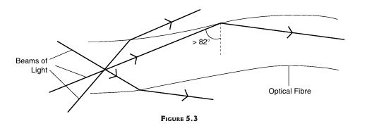
For an optical fiber whose core is made of glass and is surrounded by a plastic cladding, the critical angle is 82°. Therefore, when light hits the plastic cladding at an angle greater than 82°, it is reflected back into the same medium, i.e., back into the glass core. This is illustrated in Fig. 5.3.
An optical fiber is a dielectric waveguide with very high bandwidth. It guides electromagnetic waves in the optical spectrum, similar to how microwaves are guided by rectangular or cylindrical metallic waveguides. An optical fiber confines the propagating waves inside it by utilizing the property of total internal reflection of light from a dielectric interface (i.e., the interface between two dielectric materials), whereas waves in metallic waveguides are confined by reflection from the walls of the waveguides. An optical waveguide has a circular cross-section, designed so that the outer dielectric (cladding) has a lower refractive index than the inner dielectric (core). Due to these different refractive indices, total internal reflection occurs within the optical fiber.
The transmission of light in optical fibers over long distances is possible with minimal data loss. These fibers occupy less space and are lighter in weight compared to waveguides or transmission lines. Moreover, optical fibers have greater tensile strength. However, they are costly and require more protection than waveguides or transmission lines. Another disadvantage is the attenuation of signals in optical fibers, mainly due to Rayleigh scattering (which is inversely proportional to the fourth power of wavelength), absorption due to impurities, and radiation of light caused by the bending of the core.
Types of Optical Fibers
Topic asked in Applied Physics 2023 (CBCS/NEP) question paper Section B - 4(b) and Section E (Compulsory) - 9(h).
Optical fibres are categorised based on their transmission properties and the structure. These can be classified into two types, one of which is single mode fibre and the second one is multimode fibre. The core size is the basic structural difference in the optical fibres.
Single Mode Fiber
Single mode fiber, also known as monomode fiber, is a type of optical fiber designed to transmit only a single mode of light propagation. As the name suggests, single mode fibers restrict the propagation of light to a single mode, allowing for precise signal transmission. Single mode fibers have a narrow core diameter typically around 10 µm. This small core size ensures that only one mode of light propagation is supported, resulting in lower signal loss and higher bandwidth capabilities.
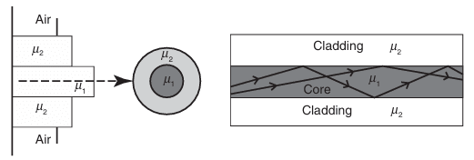
Single Mode Step Index Fiber
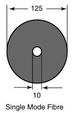
A single mode fiber is called a single mode step index fiber because the refractive index of the fiber "steps" up as we move from the cladding to the core, allowing only a single mode to propagate at a time due to the very small diameter of its core as shown in figure above. In this fiber, the refractive indices of the cladding and the core remain constant. The core diameter is typically around 10 µm. Single mode fibers have a lower signal loss and a higher information capacity or bandwidth than multimode fibers (introduced later) because the signal loss depends on the operational wavelength. These fibers are capable of transferring a higher amount of data due to low fiber dispersion.
In single mode fibers, the wavelength can increase or decrease the losses caused by fiber bending. In general, single mode fibers are considered to be low-loss fibers, which increase system bandwidth and length. Therefore, these fibers are most useful for large bandwidth applications. Since these fibers are more resistant to attenuation, they can also be used in significantly longer cable runs.
Single Mode Graded Index Fiber
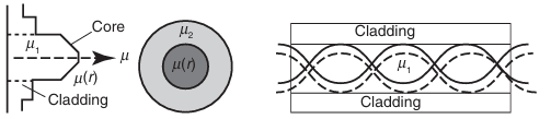
Single mode graded index fibers feature a core where the refractive index gradually decreases with increasing radial distance from the fiber axis. This design facilitates the propagation of a single mode by compensating for mode dispersion. While not as commonly used as single mode step index fibers, single mode graded index fibers offer improved modal dispersion characteristics, making them suitable for certain long-distance communication applications requiring precise signal transmission.
Multimode Fibers
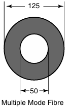
As the name implies multimode fibres allow more than one mode to propagate. Over 100 modes can propagate through multimode fibres at a time. Multimode fibre is sometimes abbreviated as MMF. The size of its core is typically around 50 mm as shown in figure above. The multimode fibre is of two types, namely step index and graded index fibres.
Multimode Step Index Fibers
Multimode step index fiber is shown in figure above, along with the refractive indices of its core and cladding. In this type of optical fiber, the number of propagating modes depends on the ratio of core diameter to the wavelength. This ratio is inversely proportional to the numerical aperture (NA, defined later). Typically, the core diameter ranges from 50 µm to 100 µm, and NA varies from 0.20 to 0.29, respectively. Multimode fiber is used in short lengths, such as those in Local Area Networks (LANs) and Storage Area Networks (SANs).
Because multimode optical fiber has a higher NA and a larger core size, fiber connections and the launching of light are easier. Multimode fibers permit the use of light-emitting diodes (LEDs). In these fibers, core-to-core alignment is less critical during fiber splicing. However, due to the presence of several modes, the effect of dispersion increases, meaning that the modes arrive at the fiber end at slightly different times, causing pulse spreading. This dispersion of the modes affects the system bandwidth. Therefore, the core diameter, NA, and index profile properties of multimode fibers are optimized to maximize the system bandwidth.
Multimode Graded Index Fibers
In a multimode graded-index optical fiber, the refractive index of the core decreases with increasing radial distance from the fiber axis, which is the imaginary central axis running along the length of the fiber as shown in figure above. The refractive index is highest at the center of the core and decreases to a value at the edge of the core that equals the refractive index of the cladding. Therefore, light waves in the outer zones of the core travel faster than those in the center of the core. This design compensates for the dispersion of the modes. Under these conditions, the light waves follow sinusoidal paths along the fiber.
In such fibers, the most common profile of the refractive index is nearly parabolic, resulting in continual refocusing of the rays in the core and minimizing modal dispersion. Standard graded-index fibers typically have a core diameter of 50 µm or 62.5 µm and a cladding diameter of 125 µm. These fibers are typically used for transmitting information over distances of a couple of kilometers. The advantage of graded-index fibers compared to multimode step-index fibers is the considerable decrease in modal dispersion.
Importance and their Applications
Topic asked in Applied Physics 2023 (CBCS/NEP) question paper Section B - 4(b).
Single Mode Fibers
Single mode fibers are crucial in modern telecommunications and high-speed data networks due to their minimal dispersion and low signal loss, making them ideal for long-distance communication.
Applications:
- Telecommunications Networks: Used in long-haul fiber optic cables, submarine communication systems, and transoceanic links, enabling high-speed data transmission over vast distances with minimal signal degradation.
- Fiber-to-the-Home (FTTH): Provides high-speed internet connections to residential and commercial users, ensuring reliable and high-bandwidth access.
- Data Center Interconnects: Facilitates large volume data transfers between servers and storage systems, supporting cloud computing and data-intensive applications.
- Industrial Settings: Employed for high-speed data transfer, remote sensing, and distributed sensing applications in automation, sensor networks, and precision instrumentation.
Multimode Fibers
Multimode fibers are used for short-distance communication and local area networks (LANs), offering cost-effective solutions for data transmission over shorter distances.
Applications:
- LAN Environments: Connect computers, servers, and networking devices within a building or campus, supporting high-speed data transfer for activities like file sharing and video conferencing.
- Storage Area Networks (SANs): Connect storage devices, servers, and switches, facilitating high-speed data transfer and supporting storage consolidation, backup, and disaster recovery.
- CATV Networks: Distribute video, voice, and data signals, enabling services like high-definition television (HDTV), video-on-demand (VOD), and broadband internet.
- Industrial Automation and Education: Support high-speed data transfer in surveillance systems, building automation, and educational resources.
- Optical Fiber Lighting and Sensors: Used in decorative lighting, signage, and biomedical sensing applications.
| Aspect | Single Mode Fiber | Multimode Fiber |
|---|---|---|
| Core Diameter | Small (typically around 10 µm) | Large (typically around 50 µm to 100 µm) |
| Propagation Mode | Supports only one mode of light propagation | Supports multiple modes of light propagation |
| Signal Loss | Lower signal loss over long distances due to the absence of modal dispersion | Higher signal loss over long distances due to modal dispersion |
| Bandwidth | Higher bandwidth | Lower bandwidth |
| Applications | Long-distance telecommunications, high-speed internet backbones, undersea cables | Short-distance communication (within buildings or campuses), data centers, some LANs, and industrial applications |
Acceptance Angle and Acceptance Cone
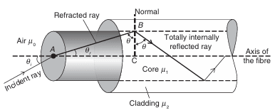
Let us consider an optical fiber into which light is incident. In above figure, we show a section of a cylindrical optical fiber. The refractive index of the core is and that of the cladding is , such that > . The refractive index of the medium from which the light is incident into the fiber is . A light wave enters the fiber at an angle with the axis of the fiber. This wave gets refracted at an angle and strikes the core-cladding interface at an angle . If is greater than the critical angle the wave undergoes total internal reflection at the interface, since > . As long as the angle is greater than , the light will stay within the core of the fiber.
Let us now compute the incident angle for which such that the light remains confined within the core of the fiber. Applying Snell's law to the launching face of the fiber, we get:
If is increased beyond the limit, will drop below the critical value (as + = 90°, in ABC) and the ray escapes from the side walls of the fibre. The largest value of occurs when . This value of we represent by max. From the ABC, it is seen that
From Eqs. (i) and (ii), we get
when = ,
At critical angle,
By putting the value of from Eq. (iv) into Eq. (iii), we get
If the incident wave of light is launched from air medium (for which = 1), then
putting in above eq, eq becomes,
or
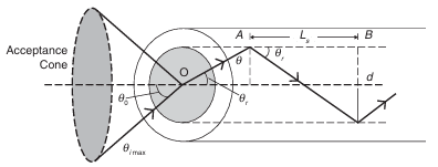
The angle is called the acceptance angle of the fiber, which may be defined as the maximum angle that a light wave can have relative to the axis of the fiber for its propagation through the fiber. The light waves contained within the cone having a full angle of are accepted and transmitted along the fiber. Therefore, the cone associated with the angle s called the acceptance cone (Above Figure). Light incident at an angle beyond refracts through the cladding. Since, at every internal reflection, the light will be lost if it is incident at an angle less than the critical angle, the corresponding optical energy is lost. It is also obvious that the acceptance angle would be larger if the diameter of the core is larger.
Numerical Aperture
Numerical aperture (NA) is the most important parameter of an optical fiber. It is a measure of how much light can be collected by an optical system such as an optical fiber or a microscope lens. Based on the refractive indices of the core and cladding, we can measure the values of NA. It is defined as the sine of the acceptance angle if the end faces of the fiber are exposed to a medium for which (air). Otherwise, the numerical aperture is defined as .
For ,
This relation shows that the light-gathering ability of an optical fiber increases with its numerical aperture. Since the maximum value of can be 1, he value of NA cannot exceed 1. This means the largest value of NA is unity. When , the fiber totally reflects all the light entering its face. Fibers with a wide variety of numerical apertures, ranging from about 0.2 up to 1.0, are commercially available.
Skip Distance
It is well known that the light propagates in the optical fibre based on the principle of total internal reflection. The light ray gets reflected from the walls of the fibre. The distance between the two successive reflections of a ray of light propagating in the fibre is called the skip distance . In above figure, the distance is the skip distance, given by
where is the diameter of the core of the fibre and is the angle of refraction in the core. We can write the above relation in terms of incidence angle and the refractive indices and by using Snell's law as
This gives,
or
Hence,
or
It is clear that the inverse of the skip distance , i.e., will give the total number of reflections made by the light ray in a given length of the fibre. For example, in a fibre of length , the number of reflections would be
For example, in the case = 1.60, = 1, = 30° and = 0.05 mm, we get the skip distance as 0.152 mm. Therefore, in 1 m of fibre there will be 6580 reflections.
Relative Refractive Index
It has been established that the refractive indices of the core and the cladding of the fibre are different. The difference of these two indices gives a measure of the relative refractive index difference. In this light, it can be obtained that
Now is very nearly equal to in view of . Further, we put in the above eq and obtain .
In term of this relation the numerical aperture can be written as,
Here is called the relative refractive index difference or fractional refractive index.
Normalized Frequency or V-Number
Normalized frequency, often denoted as V-number (V), is a dimensionless parameter used to characterize the propagation characteristics of light in optical fibers. The normalized frequency provides a measure of the number of guided modes supported by an optical fiber. It determines whether the fiber operates in the single mode or multimode regime.
Where,
- is diameter of core
- is wavelength of light propagating in optical fiber
- is numerical aperture
For single mode fibers, where only one mode is guided, the normalized frequency (V) is typically much smaller than 2.405.
For multimode fibers, which support multiple guided modes, the normalized frequency (V) is usually greater than 2.405.
If represents the number of modes in multimodemode fiber then,
- For Step Index Multimode Fiber
- For Graded Index Multimode Fiber
Propagation Mechanism and Communication In Fiber
It is not a single video but a playlist, and it contains two videos. When one video finishes, the next will play automatically.

Before the development of optical fiber communication, a general communication system was commonly used. This system consists of essential components such as a modulator or transmitter, a transmission medium, and a demodulator or receiver, as shown in above figure. However, optical fibers have replaced copper coaxial cables due to their various advantages. Optical fibers are lightweight, thin conduit cables that provide greater communication capacity with lower loss.
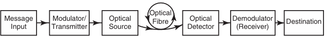
A fiber optic communication system from signal source to signal output is shown in above figure. Here, the information to be transmitted is first converted from an electrical signal into an optical signal. After transmission through the optical fiber, the optical signal is then converted back into an electrical signal. Independent of the original nature of the signal, a fiber provides the choice of format for transmission as either analog or digital because these two formats are convertible into one another.
The signal, in either analog or digital form, is impressed onto a carrier wave using a modulator. The carrier wave is generated from a carrier source, which may be either a light emitting diode (LED) or a laser diode (LD). This carrier wave is modulated using various techniques such as frequency modulation, amplitude modulation, and digital modulation. The carrier source output into the optical fiber is represented by a single pulse.
When a pulse is passed through the fiber, it is attenuated and distorted due to several mechanisms, such as intermodal distortion. Therefore, repeaters and regenerators are used to amplify the light signal at several points along the fiber. After amplification, the light signal is coupled into a detector, which may be a semiconductor device, most commonly a PIN diode, at the end of the fiber. This detector converts the optical signal back into an electrical signal.
The response of the detector should be well-matched with the optical frequency of the received signal. The output of the detector then passes through a signal processor, which is used to extract the original electrical signal from the carrier by filtering, amplification, and analog-to-digital conversion. The signal output is finally communicated by a cathode ray tube (if it is a video signal), by a loudspeaker (if it is an audio signal), or by a computer input (if it is a digital signal).
A high bit rate signal carried on a copper wire transmission line generally needs to be amplified every 300 meters. However, when high bit rate signals are carried on optical fibers, they require amplification only every 100 kilometers or so.
As discussed earlier, a detector changes the optical signal back into an electrical signal. The light signal is coupled to the detector at the remote end of the fiber. This is done effectively when the response of the detector is well matched with the optical frequency of the received signal. Then, a signal processor handles the detector output. The function of the signal processor is to recapture the original electrical signal from the carrier. This process involves filtering, amplification, and digital-to-analog conversion.
Attenuation and Losses
When light travels along the fiber, there is a loss of optical power, which is called attenuation. Signal attenuation is defined as the ratio of optical input power to the output power . Optical input power is the power transmitted into the fiber from an optical source, while optical output power is the power received at the fiber end. The signal attenuation or absorption coefficient in terms of the fiber length can be described by the following relation:
Signal attenuation is a logarithmic relationship. The length of the fiber is expressed in kilometers. Consequently, the unit of attenuation is decibels per kilometer (dB/km). The causes of attenuation in an optical fiber include absorption, scattering, and bending losses.
- Absorption: Occurs when impurities in the fiber material absorb some of the light energy.
- Scattering: Happens when imperfections in the fiber structure scatter light in different directions, causing some of it to escape the core.
- Bending Losses: Result from bending the fiber too tightly, causing light to leak out of the core.
Each mechanism of loss is influenced by the properties of the fiber material and fiber structure. However, loss also occurs at fiber connections (e.g., insertion loss, reflection loss). Absorption losses over a length of fiber can be described by the usual exponential law for light intensity (or irradiance) :
where is the initial intensity or irradiance of the light and is the absorption coefficient.
Attenuation is wavelength-dependent. Different wavelengths of light experience different amounts of attenuation in the fiber.
Losses in optical fibers refer to the reduction in optical power as light travels along the fiber. These losses can occur due to various factors and can impact the efficiency and performance of the optical communication system. Here are some common types of losses in optical fibers:
- Absorption Losses: Absorption losses occur when optical power is absorbed by the material composing the fiber. This can include impurities in the fiber material, such as water molecules or dopants, which absorb light energy at certain wavelengths. Absorption losses can also occur due to defects or imperfections in the fiber structure.
- Scattering Losses: Scattering losses occur when light is scattered in different directions as it interacts with imperfections or irregularities in the fiber material. There are two main types of scattering losses: Rayleigh scattering, which occurs due to microscopic variations in the refractive index of the fiber, and Mie scattering, which occurs due to larger imperfections such as impurities or defects.
- Bend Losses: Bend losses occur when light is attenuated as it propagates through a curved section of fiber. When light travels around a bend, it can leak out of the core and into the cladding, resulting in loss of optical power. Bend losses are more pronounced in fibers with smaller core diameters and tighter bend radii.
- Modal Dispersion: Modal dispersion occurs in multimode fibers when different optical modes travel at different speeds, causing pulse spreading and distortion. This can occur due to variations in the refractive index profile of the fiber or imperfections in the fiber geometry. Modal dispersion limits the maximum data rate that can be transmitted over a multimode fiber.
- Connector and Splice Losses: Connector and splice losses occur at points where optical fibers are joined together or connected to other optical components, such as lasers, detectors, or amplifiers. These losses can occur due to misalignment between fibers, reflections at the interface between fibers, or imperfections in the connectors or splices themselves.
- Polarization Losses: Polarization losses occur when light polarized in one direction experiences greater attenuation than light polarized in another direction. This can occur due to birefringence in the fiber material or polarization-dependent loss at optical interfaces.
Applications of Optical Fibers
Optical fibers have a wide range of applications across various fields due to their ability to transmit data at high speeds with minimal loss. Here are some key applications:
1. Telecommunications
- High-Speed Internet: Optical fibers provide the backbone for internet infrastructure, enabling high-speed data transmission over long distances with low latency.
- Telephone Networks: Fiber optics are used for transmitting voice signals with high clarity and reduced noise.
- Cable Television: Optical fibers deliver high-quality TV signals, supporting HD and 4K broadcasts.
2. Medical
- Endoscopy: Optical fibers are used in medical imaging devices to view inside the body with minimal invasion, allowing for diagnostic procedures such as colonoscopy and laparoscopy.
- Laser Surgeries: Fiber optics guide laser beams in precise surgical procedures, such as removing tumors or repairing tissues.
- Biomedical Sensors: Optical fibers are used in various sensors to monitor physiological parameters like blood pressure and oxygen levels.
3. Industrial
- Inspection and Sensing: Fiber optics are used in remote inspection of hard-to-reach areas, such as inside engines and pipelines, as well as for monitoring structural health.
- Automation: Fiber optic sensors are employed in industrial automation to measure parameters like temperature, pressure, and strain.
- Data Transmission in Factories: Optical fibers are used for fast and reliable data communication in industrial environments.
4. Defense and Aerospace
- Secure Communications: Optical fibers are used for secure and high-speed communication in military operations.
- Guidance Systems: Fiber optics are utilized in missile and aircraft guidance systems for precise navigation.
- Surveillance: Optical fibers enable high-resolution video transmission for surveillance and reconnaissance.
5. Scientific Research
- Astronomy: Optical fibers are used in telescopes and other astronomical instruments to gather and transmit light for analysis.
- Particle Physics: Fibers transmit data from detectors in large particle accelerators.
References: Engineering Physics, H.K Malik & A.K Singh, Tata McGraw-Hill , Pankaj Physics Gulati