Download Question Paper (Link Below)
Question Paper Solution
-
Apply nodal analysis to find and the power dissipated in each resistor in the circuit of given below Figure1.

-
Determine and at terminal 1-2 of the circuit given in Figure 2. Find its equivalent Norton's circuit.

Step 1: Identify
- To find , we deactivate all independent sources.
- Deactivate the 2A current source (open circuit) and the 30V voltage source (short circuit).
- The remaining resistors are 30Ω and 60Ω in parallel.
Step 2: Identify
- To find , we need the open-circuit voltage across terminals 1-2.
- Calculate the voltage drop across the 60Ω resistor using the voltage divider rule.
Step 3: Convert to Norton’s Equivalent
- Use the relationships and .
Final Answer
- Norton’s Equivalent: ,
-
For an R-C series Circuit, a D.C voltage is applied at t = 0. Find the expression for transient voltage at any time.
At , the capacitor is initially uncharged, so the initial voltage across the capacitor is volts.
Differential Equation
Using Kirchhoff's voltage law (KVL) for the series R-C circuit:
where is the voltage across the resistor, and is the voltage across the capacitor.
Since and , and noting that , we get:
Rearranging the terms, the differential equation becomes:
Solution to the Differential Equation
This is a first-order linear differential equation. The general solution for is given by:
where:
- is the applied DC voltage.
- is the time constant of the circuit.
The transient voltage across the capacitor increases exponentially from 0 volts to as time progresses.
-
(i) Find the equivalent capacitance seen at the terminal A and B in below Figure 3.

Note: In the solution provided, label "B" has been replaced with "G."
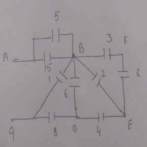
Capacitors 5 and 15 are in parallel along A and B, so the formula for the parallel capacitance is:
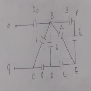
Capacitors 3 and 6 are in series along B, F, and E. The formula for the series capacitance is:
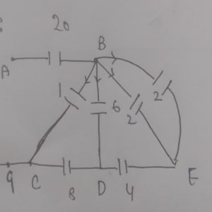
Now, capacitors 2 and 2 are in parallel connection along B and E, so:
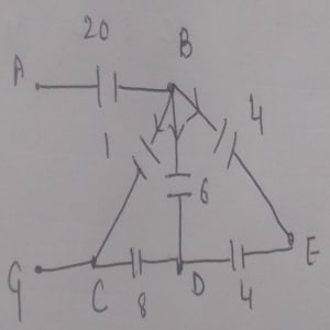
Here, capacitors 4 and 4 are in series along B, E, and D. Thus:
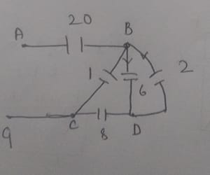
Next, capacitors 2 and 6 are in parallel along B and D, so:
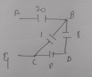
Then, capacitors 8 and 8 are in series along B, D, and C, resulting in:
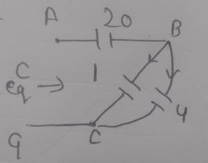
Capacitors 1 and 4 are in parallel along B and C, giving:
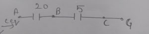
Finally, capacitors 20 and 5 are in series along A and G, so:
Therefore, the equivalent capacitance .
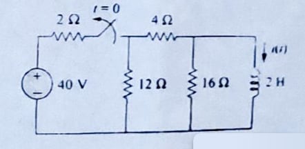
(ii) The switch in the circuit af Figure 4 has been closed for a long time. At t = 0, the switch is opened. Calculate I(t) for t > 0.
-
In the below circuit given in Figure 5 calculate -
(a) the power factor
(b) the average power delivered by the source
(c) the reactive power
(d) the apparent power
(e) the complex power

We were not able to find the exact solution for it. This numerical is based on Power Dissipation in AC circuits.
-
In the series RLC circuit, , , and and it is powered by voltage
(a) Find the resonant frequency and the half-power frequencies.
(b) Calculate the quality factor and bandwidth.
(c) Determine the amplitude of the current at , , and
This numerical is based on Resonance in Series and Parallel circuit. Here is related solution video (not exact).
-
(i) Derive EMF equation of a single phase transformer.
(ii) A single phase transformer has 180 and 90 turns respectively in its secondary and primary windings. The respective resistances are and . Calculate the equivalent resistence of
(a) primary in terms of secondary
(b) secondary in terms of primary
(c) total resistance of the transformer in terms of the primary
This numerical is based on Transformer Equivalent Resistance.
-
(i) Derive torque equation of motor
(ii) A four-pole, 500V, wave-wound DC shunt motor has 900 conductors on its armature. Calculate the speed of the motor if its armature current is 80A. The flux per pole is 21mWb and the armature resistance is
Checkout Numerical Ques 2.
SECTION - E (Compulsory)
(a) A 100W electric light bulb is connected to a 250V supply. Determine the resistance of the bulb. What do you mean by forced response?
To determine the resistance of a 100W electric light bulb connected to a 250V supply, use the power formula:
Rearranging the formula to solve for resistance :
Substituting the given values:
So, the resistance of the light bulb is 625
Forced Response
The term "forced response" refers to the steady-state behavior of a system when subjected to a constant or periodic external input (forcing function). In the context of electrical circuits, the forced response is the part of the total response that is directly related to the external input, ignoring any transient effects that occur when the input is first applied.
(b) State maximum power transfer theorem
(c) The voltage across a capacitor is . Calculate the current through it.
The current through a capacitor is related to the voltage across it by the following formula:
where:
-
is the current through the capacitor,
-
is the capacitance,
-
is the derivative of the voltage with respect to time.
-
Capacitance
-
Voltage
First, we need to differentiate the voltage :
The derivative of with respect to is:
Thus,
Now substitute and into the current formula:
The current through the capacitor is:
(d) Let the RL series circuit is switch on at t = 0 with a DC source voltage of V = 230V. What will be the current flowing through it at , if
In an RL series circuit, the voltage is applied across a resistor and an inductor connected in series. The behavior of the current through the circuit is described by:
At , the inductor behaves like a short circuit because it will have reached its steady-state condition where the rate of change of current is zero. Therefore, the inductor's voltage drop will be zero.
In this steady-state condition, the circuit simplifies to just the resistor with the applied DC voltage . The current through the resistor is given by Ohm’s law:
- DC Source Voltage
- Resistance
Substitute the given values into the equation:
The current flowing through the RL series circuit at is:
(e) What is quality factor in parallel RLC circuit at resonance?
The quality factor of a parallel RLC circuit at resonance is a measure of how underdamped the circuit is, or in other words, how narrow or sharp the resonance peak is. It is defined as the ratio of the resonant frequency to the bandwidth of the circuit. The higher the quality factor, the lower the energy loss relative to the stored energy in the circuit.
For a parallel RLC circuit at resonance, the quality factor can be calculated using the following formula:
Where:
- is the resistance
- is the inductance
- is the capacitance
- is the resonant angular frequency
(f) What is meaning of reactive power in AC circuit?
Reactive Power is the component of electrical power that oscillates between the source and reactive elements in the circuit. It is associated with the energy stored in the electric fields of capacitors and magnetic fields of inductors. Unlike active power (or real power), which performs useful work, reactive power does not result in net energy transfer over a complete cycle.
The formula for reactive power is:
where:
- is the reactive power,
- is the root-mean-square (RMS) voltage,
- is the RMS current,
- is the phase angle between the voltage and current.
(g) In a balanced △-△ system, what is the relation between phase current and line current.
In a balanced delta (Δ) system, the relationship between the phase current and the line current is determined by the geometry of the delta connection.
In a delta connection, each line current is the vector sum of the currents in the two connected phases. Specifically, for a balanced system where the phase currents are equal in magnitude and 120 degrees apart in phase, the relationship can be expressed as:
=
(h) What do you mean by time constant?
The time constant in DC circuits is a measure of how quickly the circuit responds to changes in voltage or current. It quantifies the time it takes for the voltage across a capacitor to charge or discharge to approximately 63.2% of its final value, or for the current through an inductor to reach approximately 63.2% of its final value.
For RC Circuits
In a series resistor-capacitor (RC) circuit, the time constant is given by:
where:
- is the resistance in ohms (),
- is the capacitance in farads (F).
For RL Circuits
In a series resistor-inductor (RL) circuit, the time constant is given by:
where:
- is the inductance in henries (H),
- is the resistance in ohms ().
(i) What are the parameters represented by Flemming's left-hand rule used in DC motor?
Fleming's Left-Hand Rule is used to determine the direction of force, current, and motion in a DC motor. The rule is applied as follows:
-
Thumb: Represents the direction of the motion (or force) of the conductor or coil in the magnetic field.
-
Index Finger: Points in the direction of the magnetic field (North to South).
-
Middle Finger: Points in the direction of the current flowing through the conductor or coil.
(j) When the turns ratio of a transformer is 20 and the primary AC voltage is 12V. Calculate the secondary voltage?
The relationship between the primary voltage , the secondary voltage , and the turns ratio of a transformer is given by:
where:
- is the primary voltage,
- is the secondary voltage,
- is the number of turns on the primary coil,
- is the number of turns on the secondary coil.
The turns ratio is defined as:
Thus, the secondary voltage can be calculated using:
- Turns ratio
- Primary voltage
Substitute the given values into the formula:
The secondary voltage of the transformer is: